Lesson 3: The Three Views
Pre-Reading Vocabulary
UNDERSTANDING THE WORD ”VIEW”
We will be talking about the word view in this lesson–it’s important to understand this word well. What are some of its meanings?
The word view can have several meanings:
Numbers 2 and 3 are the meanings of view that are most important for this lesson on blueprint reading. We will be looking at a part from different angles in order to see all its important features. Then we will be making drawings of the views which show those features best.
Word List
THE THREE VIEWS
| to project | to send something forward. e.g., Jack drew lines to project the front view onto the paper. |
| orthographic | having to do with right angles and perpendicular lines. e.g., An orthographic projection has projection lines that are perpendicular to the plane on which they are projected. |
| orthographic projection | the view of a part’s side projected by straight lines onto a flat surface. e.g., Blueprints are made by the use of three orthographic projections. |
| to pick | to choose, to decide which one to use. e.g., When you draw blueprints, pick three views which will represent the part. |
| maximum | the highest or greatest amount or number. e.g., The maximum number of views for a part is six.Opposite: minimum–the smallest amount |
| to image | to create a picture in your own mind. e.g., The engineer tries to imagine the kind of part a job needs. |
| intersecting geometric planes | flat surfaces that cut through each other. e.g., The sides of a box are made from six intersecting geometric planes |
| curve | a line having no straight parts. e.g., The highway has many curves as it comes down the mountain side.Related Word: curved = having the shape of a curve. |
| to label | to give information about something by writing on it or attaching a paper to it. e.g., The three views were labeled with names: front view, top view, and right side view. |
| to shade | to show variations of light, in a drawing, by darkening some parts with a pencil. e.g., The shading on an isometric drawing helps to show where the surfaces are. |
| ring | a circular line, mark, or object. e.g., Draw two concentric rings, i.e., two circles which have the same center. |
Ex. 6.3 New Vocabulary Practice
THE THREE VIEWS
A blueprint can usually give all the information needed to visualize the part by showing three views of the part. It s important: (1) to choose the correct views, and (2) to arrange the views in the right order on the drawing.
1. Orthographic projections:
When we are choosing the views, we can pick three from a possible maximum of six views. The six possible views are the views of the part seen from the front, the rear, the top, the bottom, the right side, and the left side. We can visualize the six views, if we imagine the part as being inside a glass box with six sides. Then imagine lines drawn out from each view so that the shape of that view is projected onto one of the six glass sides, like a movie picture is projected onto a flat screen. The six sides of the glass box can be thought of as geometric planes that intersect each other at right angles, i.e., they are perpendicular to each other. Each projection from the part to the plane is called an orthographic projection.
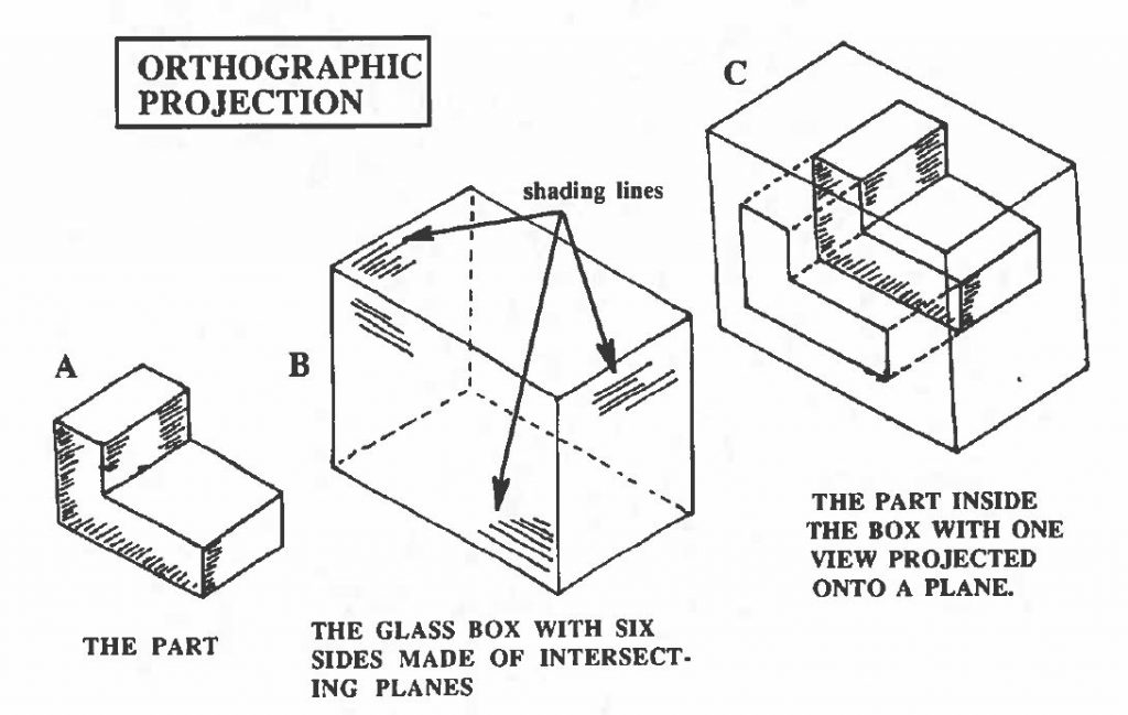
2. What is an orthographic projection drawing?
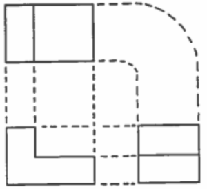
If we project all six views of the part onto the six sides of the surrounding glass box, and then open the box so that all the sides are in one plane, we will have an orthographic projection drawing. We will pick our three views from these six. Study the pictures below.
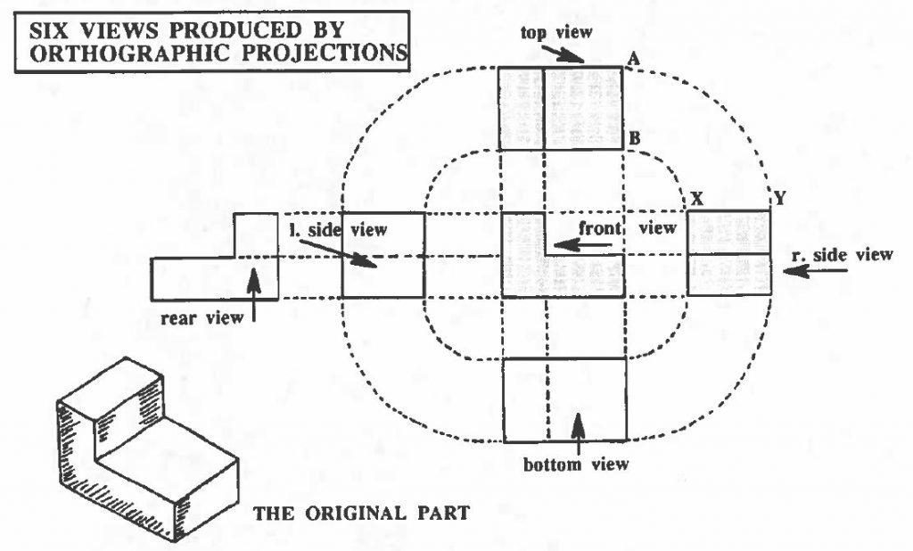
In this orthographic projection drawing the dashes which join the six views are the projection lines transferred onto paper, note how some of the dashes must be curved to show the new position of the points in the next view; e.g. points A and B in the top view become points X and Y in the right side view.
As we will see, when making a drawing you use use these dashes to take you from one part to the next, to get the correct shape of the part.
The front view is in the middle of the drawing.
The top view is above the front view.
The right side view is on the right side of the front view.This order must be followed in making and reading a blueprint whether the views are labeled or not.
3. Choosing the three views:
You can also see in the picture that three of the six views have been shaded. Why these three? The most important decision in picking the three is picking which view will be the front view. For this we need to decide which one of the six views gives the best idea of what the part looks like. The part in this picture is shaped like an “L,” so either of the two “L-shaped” views would make a good front view–we chose the one we did, so we would have a right-side view without a hidden line.
Therefore, the first step is to choose the view of the part which best shows what the part looks like; then we call that view the front view. Any of the other six views could then be drawn by projections (continuing the lines as shown in the previous picture). But what other two views will we use?
In the United States and Canada, we use the top view and the right-side view as the other two views. We have shaded these views in the drawing shown above. This is called a third angle projection and is indicated on a blueprint by this symbol: 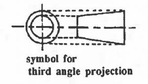
This tells us that we are operating in the USA or Canada and that this blueprint will show us the front view, the top view, and the right side view. The tapered part of the symbol is to the right of the two rings. Think of the two rings as a sun, with the tapered lines going out, like rays, from the sun to the right hand side.
In Europe and Japan, we use the top view and the left side as the other two views. This is called a first angle projection and is indicated on a blueprint by this symbol:
This tells us that we are operating in Europe or Japan and that this blueprint will show us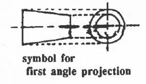 the front view, the top view, and the left-side view. The tapered part of the symbol is to the left of the two rings.
Again we will use, here in the USA, the front view. the top view and the right-side view.
Comprehension check
6.3 Drawing the Three Views
Practice Making Orthographic Projections
Read the steps for choosing and drawing the three views, as given below, for the part we looked at previously. Then on another sheet of paper, practice drawing these three views. Use this picture for your dimensions.
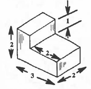
1. The first step is to decide which of the six views shows the most detail–make that view your front view:
Your thinking: You want a view that will best show the important features of the part. This part is “L-shaped,” so you will want to use one of the “L-shaped” views.
Here are the two possibilities (each shown with what would be its right- side view): 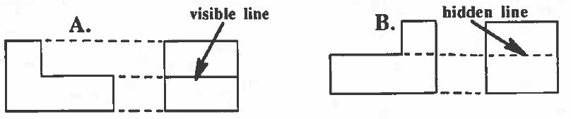
You will want to use A, rather than B, because ae right-side view of A has a visible object line rather than the hidden line in the right-side view of B.
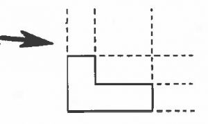
2. second step is to draw the projection lines for the other two views (the top and the right side):
 3. The third step is to draw the other two views, using the dimensions given for the original part.
5. Print this worksheet to practice drawing the views: 6.3 draw 3 views ws
Now try drawing the three views of the part given below:
Print this worksheet: 6.3 draw 3 views ws
Drawing More Orthographic Projection:
Print this worksheet: 6.3 Drawing More Orthographic Projections
More Drawing Practice:
Print this worksheet: 6.3 More Drawing Practice
Making Drawings of a Real Part:
a. Do the following:
- Get the a solid part from the teacher.
- Use the quadrille graph paper to draw the three views of a print.
- Use the steel rule to measure the dimensions.
- Label the drawing with the dimensions of the part.
Practice Conversation:
Situation: Felipe and Carlos, two machine shop students, are talking.
Conversation No. 1:
F: Carlos, come and check this blueprint I’ve drawn. It’s my first one!
C: Let me take a look, Felipe. Yes, it looks very good. Oh, wait a minute! You have three views, but they’re not arranged correctly.
F: What’s wrong with the arrangement?
C: You have the top view labeled correctly, but you put it under the front view. It goes above.
F: Oh, I see. Thanks!
C: You’re welcome. Fix that, and you’re okay. I can see you measured the lines very carefully.
Conversation No. 2:
Situation: The teacher is talking to the machine shop class.
T: Who can tell me what the words orthographic projection mean?
S: I think I can, teacher.
T: Go ahead. Use the black board, if you need to.
S: An orthographic projection is a certain view of a part. We see the view on the paper, as if it was projected onto a flat movie screen.
T: What does the word orthographic mean?
S: That has to do with two or more straight sides or planes that are per- pendicular to each other. In a blueprint drawing, the projection lines from the part are perpendicular to a plane.
T: That’s very good. You understand the ideas well.
