Lesson 5: Layout Instruments
Instrument Names
WORD LIST
| 1. blueprints | drawings, designed by an engineer, which give the specifications needed to make a part. e.g., Francisco studied the blueprints before he started to make the part. |
| 2. to lay out | to measure and draw lines on a workpiece using the dimensions given in a blueprint. e.g., The machinist laid out the lines needed to make the iron hinges.Related word: layout (the lines drawn on the rough stock showing the dimension of the part.) |
| 3. dye | a solution which contains material which will give color to what it touches. e.g., Layout dye is a blue-colored solution used to cover a workpiece. |
| 4. to dry | to go from a liquid state to a solid state with no moisture left. e.g., The Indians of North America used to dry deer meat to use in the winter. |
| 5. grease | a thick form of oil, or any smooth chemical on a part.
e.g., Before you put on the layout dye, Pedro, remove all the grease from that workpiece. |
| 6. procedure | a series of actions that you do in a certain order. e.g., What is the procedure for putting layout dye on a workpiece? |
| 7. cast iron | an alloy of iron that has been poured into a mold. e.g., Some surface plates are made of cast iron, so they must be protected from rust. |
| 8. to lap | to make a surface very flat and smooth by rubbing it with abrasive powder. e.g., A surface plate is very flat because it has been lapped. |
| 9. process | a method of doing something, usually involving several steps. e.g., Annealing is a process by which metal is hardened by heating and cooling. |
| 10. to embed | to set firmly in a surrounding material. e.g., When I fell down, I embedded dirt into my knees.NOTE: There are spellings for this word: embed and imbed. It is a word that is changing in English. Imbed is correct, but the spelling with the “e”, embed, is much more common. |
| 11. granite | a very hard rock material of gray, black or pink color. e.g., Some surface plates are made of granite which has been cut and lapped. |
| 12. powder | any dry material in the form of very small particles. e.g., Josefina put powder on her nose. |
| 13. to scribe | to scratch lines into the dried layout dye on a workpiece. e.g., Juan scribed a six-inch line at a 47° angle. |
| 14. upright | standing in a position pointing straight up. e.g., The angle plate holds the work in an upright position. |
| 15. to rest | to lie in a certain place without moving. e.g., The angle plate and the workpiece rest on the surface plate during layout. |
LAYOUT PROCEDURES
In order to make a part, the machinist must first mark the workpiece with lines showing the shape of the part. These lines will tell the machinist where to cut and drill the workpiece to make the finished part. Drawing the lines on the workpiece is called layout, because the machinist is laying out what the shape of the part is going to be.
It is important that the lines are drawn very accurately, using the exact dimensions given in the written plans for the part. (These plans are called blue prints; we will study them in the next module).
1. Layout Dye: This is a blue-colored solution which dries very quickly. The dye is brushed or 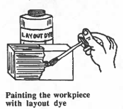 rubbed onto the surface of the workpiece. When it has dried, lines can easily be drawn on the surface of the workpiece by cutting or scratching away the dye, showing the color of the metal below. Before painting the workpiece with dye, the machinist should make sure that the surface of the workpiece is clean, dry, and free of grease, oil, chemicals, and fingerprints.
2. Punching the Layout Lines: After the lines have been drawn onto the surface of the workpiece, the machinist uses a prick punch with a point sharpened to 30° to permanently mark the layout lines. This is necessary, because the dye can be rubbed off and the lines may be lost, if the piece is handled too much.
The point of the prick punch is placed line, and the punch is hit with a ball-peen hammer. The machinist should very careful to place the point of the punch exactly on the lines especially at the points where they intersect. Next, any centers of circles should be punched using a center punch with a point-angle of 90°. These center-punched dents will give a good place for the point of a drill to start drilling. (You may want to review these punches and the ball-peen hammer which we studied in Module 3, Lesson 7.) There are many other procedures in layout that your machine shop teacher will show you.
KINDS OF ACCURACY
In the machine shop, the machinist should make all parts accurately, but sometimes he/she needs to make very accurate parts.
There are two kinds of accuracy:
1. semi-precision accuracy, and
2. precision accuracy.
Semiprecision accuracy is accurate to within ± 1/64 in. = ± 0.0156 in. of the exact dimension.
Precision accuracy is accurate to within ± 0.001 in. of the exact dimension.
If the machinist uses tolerances that are as great as ± 0.0156 in., he/she is doing semi-precision work. If the work requires a tolerance of ± 0.001 in. or less, then the work is precision work. The blueprints will tell the machinist what tolerances are required.
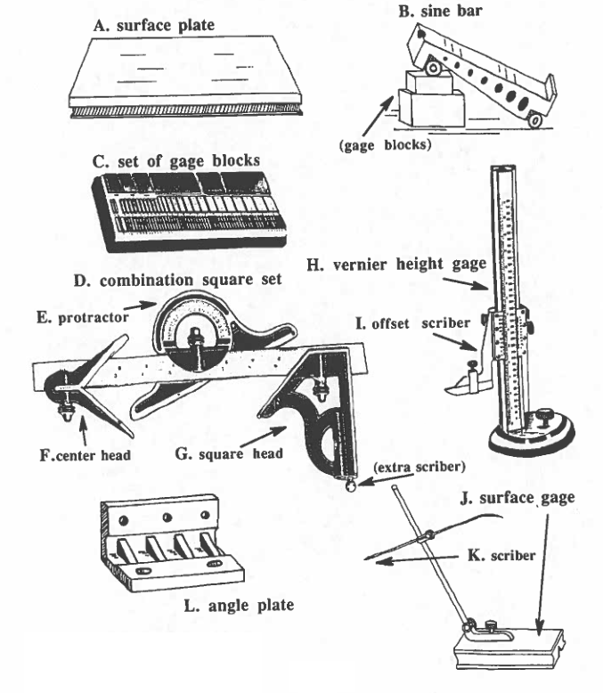
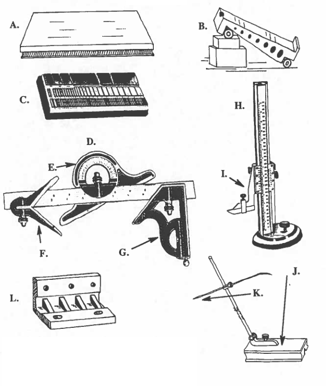
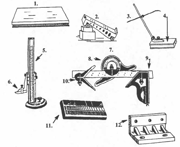
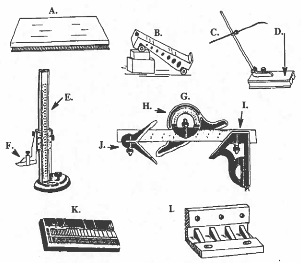
LAYOUT TOOLS (Continued)
The main purpose of this lesson is to learn a few things about the basic tools and equipment used for layout.
3. Surface Plates: To accurately use the measuring tools for layout, the machinist must have 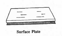 a perfectly flat surface on which to do his/her work. There are several kinds of surface plates which will provide this very flat surface. One kind of surface plate is made of cast iron; it is first machined and then the surface is lapped.
(Lapping is a process in which very small amounts of material are removed from a surface by the use of abrasive powder which is embedded in the grooves of a special plate. The special plate is then passed many times over the surface which is to be lapped. The abrasive should not remove more than 0.0005 in. of surface material. By the use of lapping, surface plates can be made very flat.)
Other kinds of surface plates are made of black, gray, or pink granite. These plates are also made by lapping. The plates are expensive, so they should be cared for well:
(1) Do not drop anything on the surface.
(2) Remove burrs from the workpiece before placing it on the surface plate.
(3) Keep in a case when not using.
(4) Maintain the plate in a clean, dry condition, especially if it is made of cast iron.
(5) Use parallels to protect the surface from sharp edges on the work-
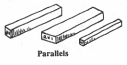 (parallels are flat bars used to raise work off the surface of the plate, but keep it parallel to the surface. They come in a variety of sizes.)
Conversation: Carlos is talking to Rufino about layout procedures.
C: Rufino, today I’m going to show you how to do a layout.
R: He, that’d be great. When do we start?
C: Right away! The first thing you do is to cut a piece of rough stock to start your workpiece. Here, saw off about 2 inches from the end of this square stock.
R: Okay! I’ve finished the sawing. Now what?
C: Next you need to make sure the workpiece is perfectly clean.
R: Yes, I’ll use this cleaning solution on the piece. There’s a film of oil all over it.
C: Good, now that it’s clean, you need to brush it with a layout dye.
R: Is that blue liquid I saw you using yesterday?
C: Yes. You’ll want to put a coat of the dye on the surface where you’re going to scribe the layout lines.
R: There! I’ve painted all the surfaces where I’ll be making layout lines. What do you think?
C: I think you’ve done very well. You’re a quick learner, Rufino. Let’s take a break while the dye is drying.
WORD LIST
| 1. precision layout | a layout in which the dimensions are within ± 0.001 in. of the exact dimensions. e.g., The vernier height gage helps the machinist to do a precision layout. (Semi-precision layout has tolerances within ± 1/64 in.) |
| 2. attachments | removable tool pieces which can be mounted on another tool or machine. e.g., My vacuum cleaner has a variety of attachments for cleaning in different places. |
| 3. slide | a part of a tool which is mounted on a bar or rod and which can be pushed up or down on the rod. e.g., The vernier height gage has a slide onto which various attachments will fit. |
| 4. beam | a supporting bar on which something else moves. e.g., The bar on which the slide moves is called the beam. |
| 5. graduated | divided with equally spaced lines or marks in order to measure a quantity. e.g., The steel rule is graduated into marks as small as 1/64 of an inch. |
| 6. carbide | a material of carbon and different metals, used to make very hard machine tools. e.g., Some cutting tools in the machine shop have replaceable carbide tips on them. |
| 7. ceramic | another material used to make machine tools; known for heat resistance and long tool life. e.g., Ceramic tools are heat resistant and long-lasting, but not as strong as carbide ones. |
| 8. to calibrate | to check or correct the graduations u a measuring tool. e.g., Every month, Constantino makes sure to calibrate his measuring tools. |
| 9. cf. | from the Latin word confer, which means “compare,” or “also look at.” e.g., When the writing says “cf., Mod. 5, Les. 2, p. 9,” you should look on that page. |
| 10. wear | a gradual loss of small amounts of material from a surface because of friction. e.g., If you touch something many times, it will gradually wear away. |
| 11. build-up | a group of blocks placed one on top of the other. e.g., Jaime used a build-up of gage blocks to calibrate his micrometer. |
| 12. to eliminate | to get rid of, to take away. e.g., You can eliminate the last digit from a number by subtracting. |
| 13. to wring together | a special term which means to make two piece of metal join together temporarily. e.g., Paloma wrang together the two gage blocks, by sliding one over the other. |
| 14. to stick together | to join two things together. e.g., The child used tape to stick together the two torn pieces of the picture. |
| 15. forward | moving toward a point in front. e.g., She drove the car forward into the parking place. |
4. Vernier Height Gage: This instrument is useful for precision layouts. A precision layout is 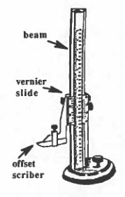 when the work is done with no more variation from the exact dimensions than 0.001 in. To draw precision layout lines, the vernier height gage has a scriber attached to a vernier slide which moves up and down on a graduated beam. Other attachments like a dial indicator or a depth gage could be substituted for the scriber when a workpiece needs to be measured or inspected.
The scriber is offset from the vernier slide so that it can be lowered all the way to the surface plate for any height measurements starting from zero at the surface of the surface plate.
5. Gage Blocks: Gage blocks are rectangular blocks of hardened steel which come in different 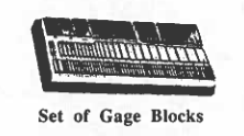 thicknesses. Each block has been very precisely cut, lapped, and polished, so it will be of the same thickness at every part of the block. The blocks come in sets, either in inches or in metric units. A common set of gage blocks has 83 pieces, all of different thicknesses (as small as
0.1001 in., up to 4.000 in.). The size of each block is stamped on its side. The blocks are sometimes made of other materials: some are chrome-plated; others are made of carbide or ceramic.
Gage blocks are very useful. They are a standard against which measurements can be made. How do you know if your micrometer is still accurate? You can use the gage blocks to see if the opening between the spindle and the anvil is accurate. (Cf. Mod 5, Les2, p. 9 for the parts of the micrometer.) If the measurement by the blocks does not match the numbers on the sleeve and thimble, then the micrometer, or any other adjustable tool, can be calibrated, i.e., you can adjust the settings to make the reading match the blocks. The gage blocks can also be used to check whether fixed gages, like the plug gages, are still accurate or whether they have been worn down by too much use.
Study this chart!
STANDARD GAGE BLOCK SIZES: 83-Piece Set
(Thickness giving in inches)
First: 0.0001-inch Series (9 blocks)
| 0.1001 | 0.1002 | 0.1003 | 0.1004 | 0.1005 | 0.1006 | 0.1007 | 0.1008 | 0.1009 |
Second: 0.001-inch Series (49 blocks)
| 0.101 | 0.102 | 0.103 | 0.104 | 0.105 | 0.106 | 0.107 | 0.108 | 0.109 |
| 0.110 | 0.111 | 0.112 | 0.113 | 0.114 | 0.115 | 0.116 | 0.117 | 0.118 |
| 0.119 | 0.120 | 0.121 | 0.122 | 0.123 | 0.124 | 0.125 | 0.126 | 0.127 |
| 0.128 | 0.129 | 0.130 | 0.131 | 0.132 | 0.133 | 0.134 | 0.135 | 0.136 |
| 0.137 | 0.138 | 0.139 | 0.140 | 0.141 | 0.142 | 0.143 | 0.144 | 0.145 |
| 0.146 | 0.147 | 0.148 | 0.149 |
Third: 0.050-inch Series (19 blocks)
| 0.050 | 0.100 | 0.150 | 0.200 | 0.250 | 0.300 | 0.350 | 0.400 | 0.450 | 0.500 |
| 0.550 | 0.600 | 0.650 | 0.700 | 0.750 | 0.800 | 0.850 | 0.900 | 0.950 |
Fourth: 1.000-inch Series (4 blocks)
| 1.000 | 2.000 | 3.000 | 4.000 |
Wear Blocks: 0.050-inch Series (2 blocks)
Gage blocks continued:
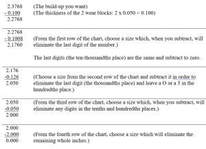
The individual blocks from the set of 83 can be used for measuring. They can also be put together in various combinations to get any one of over 120,000 different combinations. When you put the blocks together, you are making a gage block build-up. It is important to learn how to do a gage block build-up correctly. Here is an example: You want a build-up of 2.3758 inches. What blocks would you put together to reach that number. Here is the method:
First, you should put the two wear blocks on the two ends of the buildup, with the same sides facing out each time; remember to put the sides with the words on the outside. That way only those sides will get any wear; all the other block surfaces will be untouched; this method will also keep the blocks clean.
Check your work by adding the blocks you subtracted to reach zero:
0.100 + 0.1008 + 0.126 + 0.050 + 2.000 = 2.3769
Print this worksheet: 5.5 Gage Block Worksheet
Gage blocks continued:
Don’t heat up the blocks! As you know, heat causes some material, especially metals, to expand. The gage blocks were made and calibrated at 68° F. If you hold the blocks with your fingers which have a temperature of 98° F., you can cause the blocks to expand and lose some of there accuracy. A change of 1° F. can cause 4 inches of gage blocks to expand 0.000025 in.
To avoid heating up the blocks, try to handle them as little as possible. Use gloves, when you want extreme accuracy. Make sure anything that the blocks will touch (like a workpiece) is at the same temperature as the blocks.
“Wringing” together two gage blocks : The word “wring” is a special word that describes a char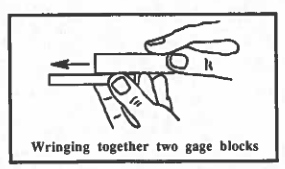 acteristic which the gage blocks have. If the blocks are very clean, they will stick together when you slide one of them over the other with pressure. Your action of sticking the blocks together is called “wringing.”
To wring together two gage blocks, wipe them with a soft, clean cloth and then pass them lightly over your wrist to pick up a small amount of oil from your skin. Press down on one and slide it forward over the one below. The two blocks should stick together. Don’t leave the blocks wrung together—they may rust. Clean them, oil them, and put them in their case, when you are finished.
MORE QUESTIONS about Gage Blocks.
WORD LIST
| 1. protractor | an instrument in the form of a semicircle, used for making and measuring angles. e.g., Eugenio used his protractor to measure the angle on the part. |
| 2. bevel | an angle on a part, other than a right angle. e.g., Pablo measured the bevel very carefully with the bevel protractor. |
| 3. level | a tool used to measure whether something is on an even horizontal plane. e.g., Use this level to make sure your surface plate is set up correctly. |
| 4. bubble | a small ball of air or gas in a liquid. e.g., The level has a bubble which moves through a yellow liquid in a glass tube. |
| 5. handy | close at hand, easy to reach, useful. e.g., It is sometimes handy to have a scriber located in a hole in your combination set. |
| 6. octagonal | having eight equal sides. e.g., This rough stock is made in long bars with octagonal sides. |
| 7. apart | separated from each other by a certain distance. e.g., The centers of the two circles were exactly five inches apart. |
| 8. height | how tall or how high something is; the altitude of something. e.g., Sofia’s height was 5′ 6″ |
LAYOUT TOOLS (Continued)
6. Combination Square Set: These tools are very useful for the machinist; the combination set 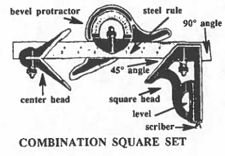 has a grooved steel rule and three tools which will fit on the rule. The three tools are the square head, the center head, and the bevel protractor.
(This is a good time to check out the combination square set from your teacher; it will be good to look at the tools as you read these pages.)
a. The Machinist’s Square: This is the steel rule with the square head in place on the grooved rule. The square is a good tool for checking 45° and 90° angles; the two sides of the square head form these two angles with the edge of the steel rule.
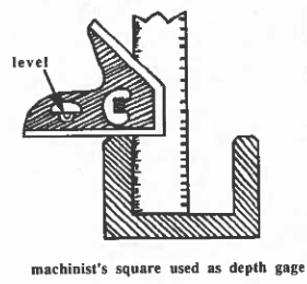 The square head and the steel rule can also be used as a depth gage for holes, slots and recessed parts into which the end of the steel rule will fit; it would of course not fit into something like small holes. The steel rule has four different inch scales on it: eighths, sixteenths, thirty-seconds, and sixty-fourths. The steel rule can be put into into the square head two different ways, so the machinist can use any one of the four scales. A knurled nut will loosen or tighten grip on the steel rule.
The square head also has a level to let the machinist know if the square head is level on the work piece. When it is level, the bubble inside the fluid will be exactly between the two black lines on the yellow glass.
The square head and steel rule can also be used to make a quick check of squareness: The rule is inserted into the square head. The edge of the rule and the square head form a right angle; this 90 angle can be placed against the side of a work piece which is resting on the surface plate; if the side of the work is at a right angle to the surface plate, no light will show through — if you can see light, the side of the work is not square with the surface plate.
The square head and rule can also be used (1) to lay out lines parallel to an edge and (2) to lay out lines at a 45° or 90° angle to the edge. We will practice this soon.
The square head also has a scriber hidden in it. Take a moment now to find the scriber, pull it out, and replace it. It is in a handy place for use in laying out lines on a workpiece which has been painted with layout dye.
b. The Center Head: If you take the square head off the rule and put the center head on the rule, 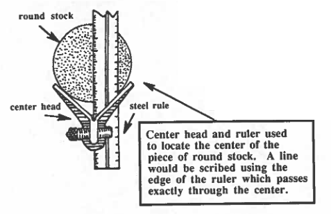 you will have a center square which can be used to draw two lines which will intersect at the center of any piece of round, square, or octagonal stock. If you scribed these lines on the end of the stock you could center punch the intersection and have a place for drilling a center hole.
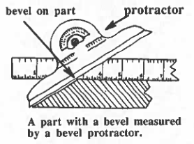
c. The Bevel Protractor: This instrument, mounted on the grooved steel rule, is used for laying out and checking any angles from 0° to 180°. The accuracy of this protractor is to within ± 30′ (minutes) of the exact angle. There are other protractors available, if greater accuracy is required.
USING THE COMBINATION SQUARE SET
Print this worksheet: 5.5.16 Comb Square Worksheet
QUESTIONS on the Combination Set Square.
LAYOUT TOOLS (Continued)
7. Sine Bar: If greater accuracy is needed in measuring and scribing angle lines during layout, there is another tool besides the protractors-it is the sine bar. A sine bar is a bar of steel with two steel cylinders of equal diameter fastened at each end of the bar. The centers of the two cylinders are exactly parallel to the edge of the sine bar and also parallel to the surface on which the tool rests. The centers of the two cylinders are made to be either 5 inches or 10 inches apart. When using a sine bar, machinists will place it on top of a surface plate. By using a sine bar, a machinist can scribe angles which are accurate within 5′ of one degree.
As you can tell from the name, the sine bar uses principles of trigonometry to calculate the correct angle. (If you do not remember well the lesson we had on trigonometry, this would be a good time to review it–Module 4, Lesson 7.)
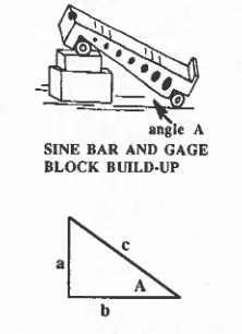 As you remember, trigonometry studies the sides and angles of right triangles. When the machinist uses a sine bar, he/she forms a right triangle during the layout on the surface plate: The hypotenuse of the triangle is the length of the sine bar itself (either 5 or 10 inches); the adjacent side is the surface of the surface plate; and the opposite side is made from a build-up of gage blocks under one end of the sine bar; angle A is the angle formed by the sine bar and the surface plate.
The machinist can make the angle very accurate if he/she can figure out the height of the gage block build-up, i.e., side a in the right triangle on the left. The sine bar and gage build-up can then be placed next to the work and the correct angle line can be scribed. This will only be accurate if done on a surface plate.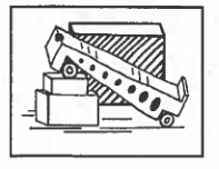
Because we know the relationship of the sides and the angles, as expressed in the trigonometric functions, we can compute the height of the gage block build-up, if we want to form a known angle. Let’s look below.
Calculate the Height of the Gage Block Build-Up
When we look at the sides and the angles of the triangle above, we see that the following statements are true:
a = opposite side = gage block build-up;
b = adjacent side = surface plate;
c = hypotenuse = sine bar = 5 in.
and
sin A = opp/hyp = a/c = a/5
Let’s solve the above equation for a (using algebra):
1. Rewriting in simple form: sin A = a/5
2. Multiplying both sides by 5: 5(sin A) = 5(a)/5
3. Canceling the 5s: a = 5 sin A
Or
gage block build-up = 5 x the sine of angle A
Calculator Input: 5 x Sin (# of angle A)
Here is a sample problem:
Calculate the gage block build-up needed to form an angle of 36° using a 5-inch sine bar.
(1) Write down the formula: a = 5 sin A
(2) Substitute know values: a = 5x sin 36°
(3) Find the value of sin from the trig tables: a = 5 x 0.5878 = 2.939 in.
Calculator Input: 5 x Sin 36
You have learned that to form an angle of 36°, you need a gage block build, up of 2.939 inches at the end of the 5-inch sine bar, placed on a surface plate.
