G43 and H codes: Tool Offsets
Code Practice 4
OBJECTIVE
After completing this unit, you should be able to:
- identify Tool Length Offsets
- identify Tool Height Offset Compensation
- recognize Tool Length Offset register
Terminology Note
You are learning about setting up a CNC mill and lathe. The tools must be measured. You will hear different terms for this measurement:
1) Tool Length Offset,
2) Tool Height Offset, and
3) Tool Height Offset Compensation (in your IMTL-134 textbook, Lesson 2, pg. 4)
4) Tool Length Compensation
It can be helpful to think about the tool measurement using the word “height” because it relates to the CNC code “H” in your CNC program. This helps explain why the H# must match the T# in the program. The computer needs a command (a code) to find the specific information (tool length or tool height) for each tool. The register is the place or file in the computer where the offset measurements are stored.
The Tool Length Offset is the measurement.
The Tool Height Offset Compensation refers to the math calculations the computer does with the tool measurements. It’s code is G43.
The Tool Length Offset register is the computer file or database for the tool measurements.
Tool Length Offsets (TLO)
Every tool loaded into the machine is a different length. In fact, if a tool is replaced due to wear or breaking, the length of its replacement will likely change because it is almost impossible to set a new tool in the holder in exactly the same place as the old one. The CNC machine needs some way of knowing how far each tool extends from the spindle to the tip. This is accomplished using a Tool Length Offset (TLO).
G43 is the code which directs the CNC controller to find the tool length for the tool that is about to do some cutting.
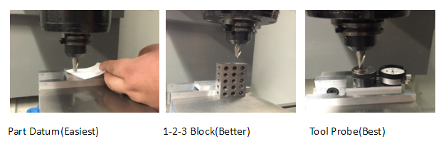
3-WAYS TO SET TOOL LENGTH OFFSET
In its simplest use, the TLO is found by jogging the spindle with tool from the machine home Z-position to the part Z-zero position, as shown on the far left in Figure 1 below (Part Datum). The tool is jogged to the part datum Z and the distance travelled is measured. This value is entered in the TLO register for that tool. Problems with this method include the need to face mill the part to the correct depth before setting tools. Also, if the Z-datum is cut away (typical of 3D surfaced parts) it is impossible to set the datum should a tool break or wear and need to be replaced. All tools must be reset whenever a new job is set up. When this method is used, the Fixture Offset Z is not used, but set to zero.
The method shown in the center of Figure 1 below (1-2-3 Block) is much better. Your shop videos have an example of this method. All tools are set to a known Z-position, such as the top of a precision 1-2-3 block resting on the machine table. This makes it very easy to reset tools if worn or broken.
A tool probe is seen in the right-hand picture of Figure 1 below (Tool Probe). It is very similar to the 1-2-3 block method, except the machine uses a special cycle to automatically find the TLO. It does this slowly lowering the tool until the tip touches the probe and then updates the TLO register. This method is fast, safe and accurate but requires the machine be equipped with a tool probe. Also, tool probes are expensive so care must be taken to never crash the tool into the probe. You also have an example of this in one of your shop videos for set up.
Both the 2nd and 3rd methods also require the distance from the tool setting position (the top of the 1-2-3 block or tool probe) to the part datum to be found and entered in the Fixture Offset Z. The machine adds the two values together to determine the total tool length offset. This point will be explained later in your CNC training.
Tool Length Offset Register (H code)
G43 activates tool length compensation. It is always accompanied by an H-code and Z-move, where H is the tool length offset (TLO) register to read, and Z is the position to go to in reference to the part datum.
It is important to match the T# to the H#. The CNC controller uses the measurement in the register (H-code) to calculate the Tool of the same number (T#).
The TLO registry looks like a table on the screen:
Table 1: Tool Offset Register
|
Tool Length Register |
Z |
|
H1 |
10.236 |
|
H2 |
4.7510 |
|
H3 |
6.9652 |
|
H4 |
7.6841 |
|
H5 |
12.4483 |
|
H6 |
8.2250 |
The TLO in the registry is the information the machine needs to knows where the tip of the tool is in relation to the part datum.
For example: G43 H1 Z1.
G43 says to find the tool length information. H1 says to look in the Tool Length Offset register under a specific number. Then, Z1 puts the tool into that position.
Section Question
H.) Name three ways to set Tool Length Offsets.
Adapted from “Vertical Milling Center Machine Motion” by LamNgeun Virasak, Manufacturing Processes 4-5 is licensed under CC BY-SA 4.0
