Introduction to Turning Machines aka CNC Lathes
OBJECTIVES
After completing this unit, you should be able to:
- Identify and describe parameters on CNC turning center (lathe)
- X and Z axes
- Point of origin
- Common quadrant
- Feedrate differences
- U and W words
- X value
- Constant Surface Speed application
CNC Lathes
For lathe programming, a lot of the codes and the variables are the same. For example, absolute and incremental positioning are the same on the mill and lathe.
However; there are many differences.
CNC Lathe Code Details that are different than mill codes.
X and Y axes on a lathe
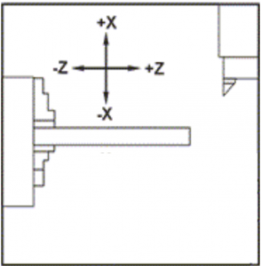
Cutting path for a lathe has the standard two axes: X and Z.
X is up and down
Z axis is left to right
Point of Origin: Zero is center of part.
Quadrants:
Most programing on the mill occurs in Quadrant IV.
On the lathe, Quadrants I and II are common.
Feedrate difference is a key issue:
Feedrates on mill = IPM, e.g. 8, 32, 54
Feedrates on lathe = IPR
On the manual engine lathe, F values are small because its inch per revolution.
On the CNC, Lathe F values should not be in whole numbers. e.g. .005, .006, .007
Z movement command relates to W
Review G90 and G91
Positioning in CNC Code
- G90, Z moves in cardinal numbers on line
- G91, Z moves based on previous position
On the FEMCO lathe, codes U and W to make adjustments. U is for X and W is for Z. There is an ability to use these codes. Sometimes, G90 is used.
Remember
A radial cut means the cut is only on side of the round part.
The total reduction is in the diameter.
X values on the lathe are different, too.
Lathe doesn’t program the x value intuitively.
X values are now diameter values. It’s a 2:1 ratio.
X = diameter value (not radius)
Count diameter values for features???
Another big change is with lathe headers.
Two types of lathe headers to choose with or without Constant Surface Speed – CSS.
(Details are in the next section of the book.)
Speaking of the header, just a heads up. There is no H code, no H word, on the lathe. The tool number captures the tool length offset or tool length compensation by using the offset number in the T code.
For example, T0101 Tool #1, Tool Offset #1
T0202, Tool #2, Offset #2.
And, so on.
(PIC)
X1, Z0
X1.5, z-.25
1.5, Z-.25
1..5 Z-3.0
X1.8, Z -3.0
X2, Z -3.1
