G81 Drilling Canned Cycle / G80 Cancel Canned Cycle
OBJECTIVES
After completing this unit, you should be able to:
- Identify and describe G81 Drill Canned Cycle for CNC code
- Identify and describe G80 Cancel Canned Cycle
- Identify Z-depth for a center drill
- Calculate Z-axis (part thickness + radius of drill) for thru holes
- Write a three-part CNC program using G81 canned cycle code
G81 Drill Canned Cycle
Variables in G81
G99 – R-plane Return after the drilling operation is complete
F = Feedrate in inches per minute (IPM) or Metric (mm)
R = Position of the R plane for drilling operation to begin (tool out of the hole, above the part)
X = X-axis motion
Y = Y-axis motion
Z = Position of the Z-axis at the bottom of hole
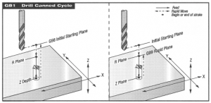
G81 Uses
The CNC code G81 is used with center drills and drilling operations. These would be different tools in the CNC machine, so two sections of the program would use G81. One section for the center drill. Another section for the drill tool.
Drilling a hole is a two-part operation. One block (of code) is for the center drill. The following block (of code) is for drilling.
The operation drills to center of tool. The program will not use G41 or G42.
The drill is 118°. The tip of the center drill is used. This makes sure that all surfaces on the second cut with the drill tool will have contact with workpiece. A 118° center drill has more surface contact than a 60° drill.
The Z is only -.05, which will only use the tip of the center drill. This is the depth for the center drill.
G80 Cancels Canned Cycles
A canned cycle is modal and must be cancelled. G80 deactivates all canned cycles. The code appears in the footer.
For example:
| T1 M06 (5 CD) [Center Drill = CD]
G90 G54 X .75 Y -1 (hole #1) S1000 M03 G43 H01 Z1.0 M08 |
Header |
| G81 G99 R.1 [start feed] Z-.05 [described above] F10 [drills 1st hole]
X # Y# [coordinates for other holes] |
Body |
| G80 G00 Z1.0 M09 [Cancel canned cycle]
G28 G91 Z0 M05 M01 [program is not ending because we need to drill.] |
Footer |
Above is just the center drill.
Holemaking is a two-step operation.
The drilling operation, the second step, is below.
| T02 M06 (1/2″ drill)
G90 G 54 G00 X Y [hole location] S???? M03 [Use CNC speed chart from lab portion of class] G43 G02 Z1.0 M08 |
Header |
| G81 G99 R .1 Z -.625 F20 [canned cycle command for drilling operation.]
X Y [locations for all holes] |
Body |
Drill Depth (Z-.625 above) explanation
The code must compensate for the angle on the tip of the drill.
For a thru-hole, the Z (depth) needs to push the tip of the drill past the opening on the bottom of the part. That part of the hole must also keep its measurement.
To keep calculations simple, let’s calculate the angle of the tip of the drill to 90°. It is easy math.
The calculation is this: part thickness + radius of drill = Z for thru hole.
In the example above, the thickness of the workpiece is .500 (it was not given above) and the radius of a 1/2″ drill is .125.
Therefore, .500 + .125 = .625 for the Z in the negative (-.625).
Shop Talk
The code will “shoulder past the end of the part.”
This means that the drill will go past its tip to make sure the thru hole is cut to the same diameter at the bottom of the part.
| G80 G00 Z1.0 M09 [Cancel canned cycle]
G28 G91 Z0 M05 M30 [End of program] |
Footer |
Other Drill Angles to Consider
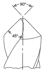
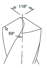
(Image source: https://www.regalcuttingtools.com/learning-center/articles/which-drill-point-angle-should-i-be-using)
In each of these images, we see the angle and the radial angle listed.
Drills are 118°. Remember from complementary angles that an angle of 118° has 72° as its complementary angle. Complementary angles must equal 180°.
The 90° angles will have 90° angles as their complementary angles.
A 90° angle is steeper than a 118° angle. The measurement of 90° will drill down a little more than the 118°. That’s fine for the indentation of a center drill. Ninety degrees allows the operator to use easy, intuitive math for the center drill Z-depth.
Center drills and Spot drills are not identical.
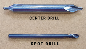
Examples of center and spot drills
Center drills have a small diameter pilot point, which contacts the material first. This creates a narrow, shallow hole that acts as a starting point for the hole. This pilot point is small, cutting easily into the material with a drill point angle of 118°.
A Spotting Drill’s purpose is to create a small divot to correctly locate the center of a drill when initiating a plunge. However, some machinists choose to use these tools for a different reason – using it to chamfer the top of drilled holes. By leaving a chamfer, screw heads sit flush with the part once inserted.
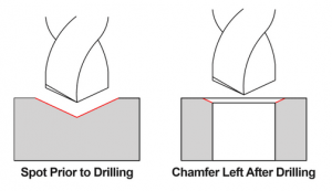
Image of spot drilling as a chamfer technique
In the following exercise, the use of a spot drill will produce the chamfer as shown above.
G81 Practice
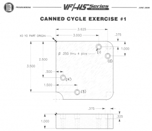
G81 Canned Cycle Exercise
S1604
F6.5Tool 4 is a 1/4″ dia. drill. Drill a thru hole to a 1.125 depth. Use a G81 canned cycle.
S2903
F14.5Tool 5 is a 3/8″ 2-flute end mill. Drill to a .325 depth. Use a G81 canned cycle.
S2037
F12.2

