G71 Roughing Cycle
OBJECTIVES
After completing this unit, you should be able to:
- Identify and describe G71 Roughing Cycle variables
- Identify and use N words within P and Q variables in G71
- Identify finish allowance
- Apply finish allowance to U and W words in G71
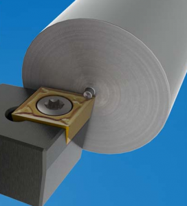
G71 Roughing Cycle on the Lathe
Variable List
P = Start place of the rough cut. It uses a number (e.g. N1, N2, etc.) to define the profile (outside shape) boundary of the part. The boundary is about a measurement. (Where does it start?)
Q = End line number (e.g. N5, N6, etc.) Where does the profile (outside shape) end? Include (add) the finish allowance (this is a measurement) for finish cut.
D = Depth of Cut. Radial value (e.g., .100 means removal of .200 of material). For formula is: DOC = 10 * roughing feed rate (generally).
U = X-axis Finish Allowance. Diameter value.
W = Z-axis Finish allowance (longitudinal). Diameter value.
F = Feed
G71 roughing cycle on the lathe can be called “auto turning cycle”. It is not a repeating cycle in the way that peck drilling is.
G71 needs some parameters so it does not cut into the true profile of the part.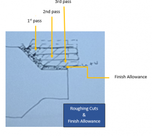
D is amount for each pass. It is the tool movement for a cut, taper, or angle.
The tool will return for another pass.
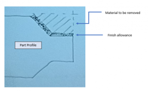
Define boundary. Dark areas are U and W.
U is the angled portion related to X-axis.
W is the longitudinal portion related to Z-axis.
What are P and Q?
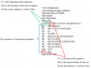
P and Q use numbers to define the start and stop boundaries. These numbers come from the N# at the beginning of lines of CNC code. In the code, they appear on the left as N followed by numbers.
For example, N1, N2, N3, N4 etc. They represent a sequence of motions. The N#s identify each step in a sequence. They are a type of an address code.
The N addresses were very useful when the early Numerical Control (NC) machines used paper for their programs. The N addresses are not always automatically put into a program with modern CNC machine tools. Programmers and operators have the ability to add N addresses to any sequence of moves in a CNC program. It is possible to use any number and continue with each step.
It depends on the CNC machine and controller that is used. The program might insert the N address. If it does not, then the programmer/operator may insert the N address as needed. In this case, a G71 command needs the start and top boundary. The roughing cycle needs the information of where to begin and where to stop its cycle. The start and stop positions or boundaries are identified by the N address numbers.
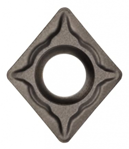
Cutting Tool Angles
G71 is a roughing operation. It is going to remove as much material as possible. The common tool or insert is 80°.
Compare the angles for 55° and 80° angles.
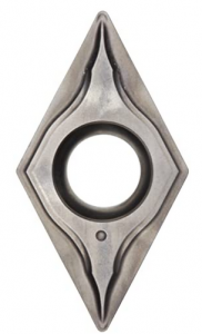 Used for finishing operations |
 |
Helpful Videos
Watch from 00:24 to 1:15. Then, watch from 5:40 to 10:30. 4476 Canned Cycles.
Watch this 12:43 video about The G71 Roughing Cycle on a CNC Lathe Explained.
Watch this 6:51 video by Tom Stikkleman: CNC LATHE PROGRAMMING LESSON 2 PART1 OF 2 – G71 CANNED CYCLE FOR OD ROUGHING
Example Program:
Other info:
DOC .100
Finish Allowance: All axes (X and Z) = .010
|
G28 T0101 (80 degree roughing) G50 S4000 G97 S 500 M03 G54 G00 X3.2 Z1.0 M08 G96 S600 (starts to vary from finish cut here) (Do not worry about continuous tool path. Start outside in, easier on tool. With roughing, approach from OD and cut in.) F.008 |
Header for Roughing |
|
Z.01 (off face) [You ALWAYS face the part] G01 X -.062 F.008 (first cut always [roughing] facing) go past X0 to remove nub (See note below.) G00 Z .1 (clearance plane = .1) X 3.0 (stock diameter) |
Facing |
|
G71 P 001 Q N003 D .100=radial value (removes .200) U .020 (diameter value) W .010 F.008 (add N # {e.g. N001 = P value} ) X 1.5 Roughing diameter. Then move Z (N002) Z-1.5 (N003) X 3.0 Q number X 3.2 (need explanation) |
Rough cycle starts now (set boundary) |
|
G00 Z1.0 M09 G28 M05 M01 |
Footer |
Shop Talk
(Image: https://www.shars.com/cnc-lathe-gage)
When your lathe cutter does not go past point of origin (0, 0), there is a type of burr or a nub left at the center of the face. This wee bit of metal is also called a “witness”.
