G54-G59: An Introduction to Coordinate Systems
Code Practice
Objectives
- Identify G54-G59 codes for specific workpiece locations on the table
- Describe importance of matching G54-G59 codes with work offset registry.
NOTE: For IMTL136, it is only required that students understand that G54-G59 codes are very important in the header. For this class, only one part will be loaded onto the CNC table.
The Two Coordinate Systems of a CNC Machine Tool
The CNC machine has two coordinate systems. One of them is preset by the manufacturer of the CNC machine tool. This coordinate system is called the machine coordinate system. It is a default coordinate system. The CNC machine will use the machine or default coordinate system to send the spindle to machine home. Operators do not set, reset, or choose machine coordinate systems.
Machine coordinate systems are defined by the geometry of the CNC machine. The machine “knows” where it is within its own coordinate system by a series of limit switches and encoders that are located on each of the axes. When they are powered up, most machines go through a homing cycle in in which they move each axis until it hits a limit switch. The coordinate system that is built into the machine is called the machine coordinate system.
The other coordinate system is the workpiece coordinate system or work coordinate system. CNC operators control this coordinate system by setting the axes for X, Y, and Z. These settings are called work offsets. It is important for CNC operators to recognize the relationship of the workpieces on the table and the measurements in the work offset registry.
Establish The Work Offset Coordinate System with G54 – G59
A CNC program could be written that uses the machine coordinate system, however this would not be practical since the machine coordinate system has an origin that is nowhere near the workpiece.
Fortunately, it is easy to define a coordinate system that aligns with the work to be machined. This is most easily done by defining a work coordinate system(s) by the use of the G codes G54 through G59. Sometimes work coordinate systems are defined relative to some permanent or semi-permanent fixture (such as a vise) attached to the machine table. Other times a work coordinate system is defined relative to a particular workpiece after it has been loaded into the machine. The second method is more common for a job shop or “one of a kind” production run.

G54 – G59 Work Offset Registers
The easiest way to use work offsets is to store them in the work offset register. This is done by positioning the machine at the exact place where the desired coordinate system origin is and having the machine record the distance between that point and its own machine coordinate system. A typical offset register screen is shown below.
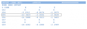
Work offsets are data registers in the CNC control that hold the distance from the machine home X, Y, Z position to the part datum. These offsets can be thought of like a table on the control.
The controller records the distance the machine is from its home position in the register that is displayed on this screen. Notice each row has a corresponding “G Code.” This code is how the programmer uses the work coordinate system origin stored in the register. The values for X, Y, and Z that are on the screen are the distances between the machine origin and each work coordinate system origin.
With the offsets defined in the offset register, the programmer can now make use of the coordinate system origin of his or her choice. When using this method, there is no need to enter the actual distances between the machine and work coordinate system origins into the actual program. All the programmer needs to enter is the G code that corresponds to the correct offset (in this case, we will be using G55).
https://www.youtube.com/watch?v=EI2inCb0Wfs
The X and Y values represent the distance from the machine home to part datum X, Y. The Z value is the distance from the tool reference point (for example, the top of a 1-2-3 block) and the part Z-datum.
For example: G54 X0. Y0.
Questions
1. Describe G54 – G59 codes.
2. Describe the Work Offset Registry
Expanded Explanation
When writing a program, programmers and operators need to inform the computer and controller how to align the coordinate system(s) of (s) with the coordinate system of the machine. The commands for directing the computer to the correct position of the workpiece(s) are the G54 through G59 codes.
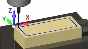
In this case, we will use the upper left corner of the workpiece as our work coordinate system. Notice this puts our work in the fourth quadrant. (See Axes and Quadrants section for this topic.) All of our X values will be positive and all of our Y values will be negative. Our Z axis origin is located at the top surface of the block. This will give all our cutting depths negative Z values. I have chosen to use the fourth quadrant because of the type of workholding I am using. Our work is being held in a vise that has one fixed jaw and one movable jaw. If I locate the origin on something more or less permanent, I won’t have to go through the as many steps when I tell the machine tool where to put the origin each time.
It is worth noting that the programmer has the choice of where to locate the origin, but little choice over the direction of the axes. These are established by the physical arrangement of the machine.
Now that we are satisfied with the location of our origin, we need to let the machine know where it is. This will be done setting the work coordinate system offsets in the work offset registry.
Adapted from “Writing a CNC Program” by ManufacturingET is licensed under CC BY-SA 4.0
