G02, G03 Four Questions
Code Practice
OBJECTIVE
After completing this unit, you should be able to:
- Use four questions to write a code to cut an arc
Terminology
- Arc: A curve. A round angle. A part of a circumference of a circle.
E.g., An arc can go around the outside (profile) of a part.
An arc can go into a part. It might look like someone took a bite out of a part. - Mode: This is the root word for modal. Remember that a CNC code stays active when it is modal. CNC users (programmers, engineers, operators) will use the word mode to describe the way the machine will move.
E.g., G00 is a modal command. The program is in the G00 mode.
G01 is the modal command for cutting. The machine is in the G01 mode.
G90 and G91 are modal. The machine can only be in one mode. - Equidistant: At equal distance to a point.
E.g., Any point on a radius is equidistant to the center point.
G02 and G03 Circular Motion are modes for the CNC Machine.
G02 establishes a mode for clockwise circular arcs.
G03 establishes a mode for counter-clockwise circular arcs.
Like the G01 command, G02 and G03 require a feed rate (F). The feed rate will default to the previous feed rate in the code.
Also like G01, the G02 and G03 codes need coordinates (X, Y, and/or Z). However, the CNC code uses different letters to identify the center of an arc.
X = I
Y = J
Z = K
I, J, or K identifies the center of the arc from the starting point of the arc.
There are two different ways to program a G02 or G03. For this class, we will only talk about and practice one of them, which is the I, J, K Method.
I, J, K Method
Only two of I, J, and K will be used.
The I, J, and K codes identify the DISTANCE from the ARC START POINT to the CENTER POINT of the arc. This distance from the start point to the center point is called “offset.”
EXAMPLE OF CLOCKWISE ARC:
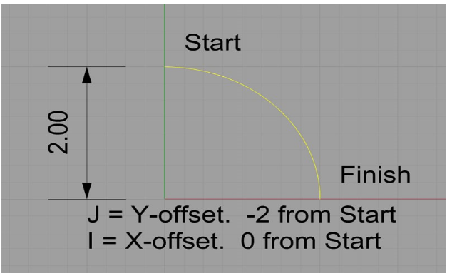
(Image: “CNC Language and Structure ” by LamNgeun Virasak, Manufacturing Processes 4-5 is licensed under CC BY-SA 4.0)
This arc starts at X0 Y2.
It finishes at X2 Y0.
Its center is at X0 Y0.
We could specify it in G-code like this:
G02 (Set up the clockwise arc mode) X2 Y0 I0 J-2.0
Four Questions
Another Example:
Assume the machine is currently at X0.0 Y0.0 and G90 is enabled in the header.
G01 Y1.0 F8.0;
G02 X1.2803 Y1.5303 I.750;
The code above will produce the following toolpath. Notice the value for J (the distance in the Y axis) would be zero. It can be omitted.
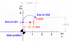
(Image: “CNC G Code: G02 and G03” by ManufacturingET is licensed under CC BY-SA 4.0)
Four Questions
When the G02 or G03 mode is in the code, arcs are defined by identifying their two endpoints. The endpoints are easy. In the program, the first point (location or position) where GO2 or G03 is used identifies the first endpoint. The first point begins the circular cut to make the arc on the part. The second endpoint uses XYZ coordinates. The second endpoint is where the arc stops.
The center point must be equidistant from each endpoint. The center is identified by using I, J, or K to establish measurements (a.k.a. “relative offsets”) from the starting point of the arc to the center. The computer will calculate the starting point to the center. It will compare the center point to the endpoint coordinates. The computer will calculate if those two measurements are equidistant.
Questions
Adapted from 1) “CNC Language and Structure ” by LamNgeun Virasak, Manufacturing Processes 4-5 is licensed under CC BY-SA 4.0; and 2) “CNC G Code: G02 and G03” by ManufacturingET is licensed under CC BY-SA 4.0
