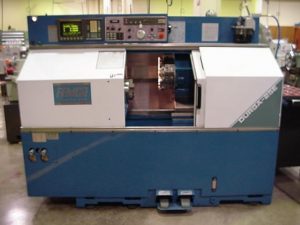
Femco Durga 25E CNC Turning Center
The Femco Durga 25 CNC Turning Center has a Fanuc-style controller.
Transcript:?
FEMCO DURGA TURNING CENTER
Ok to begin the machine and were talking about the femco durga 25e cnc turning center
The first step is to turn the master power on using this switch. When you turn that on you will notice that there’s motors start and fans inside the control unit that begin turning and you can hear the motors running.
Now that the main power is on the back of the machine tool, our next step is to turn the power on the front of the machine. We push the start button. The first time it activates the computer control unit, it runs through a diagnostics process. It prepares itself for successfully executing programs and commands that will be in the cnc code. We give this a few minutes to or you know up to a minute a to initialize the computer.
Then we press the button a second time, oh it did nothing because the emergency stop button is pressed turn the emergency stop off. Press the button a second time, and we hear the hydraulics come on. Now the machine tool is ready to align the axis.
Now something that is important to observe when we get to this step in the process is the location of the turret. The turret is located right now at the zero return or home position which means that if I just simply begin to zero return the machine it’s going to give me an overtravel on the axis. So what I need to do is move it away from the ? switches that you find in the zero return position. To do that, I choose the selector switch move it to the? Mode I select the z axis using this axis selector switch and using the hand wheel I move it in the negative direction this moves the turret forward so it is off of the ? switch ? the zero return is located. I then move the selector switch to the x axis once again moving it in the negative direction I move the turret to the center line of this spindle with this done I have cleared the ? switches for the zero return position I now move my selector to the zero return which looks like a target ? origin I press x positive first which begins movement you will notice on the ? the axis is updating once it begins moving slowly you can let go of the button and it will continue to travel if it’s going faster and you let go of the button it’s going to stop. Next I press ? plus. Now if I take my finger off it stops just like we just observed I’m gonna press and hold down as soon as it begins moving slowly then I can take my finger off the button and the machine is automatically going to drive the z axis slides so that it finds the zero return point that is factory preset and used for calibrating the measurement system of the machine tool. Now that the machine tool has been ? I need to look at my coordinate positions on the screen. I have three options I have absolute coordinates which are pictured as the default at start up it gets me the position of the machine along the x axis which factory preset is x eight point zero zero inches and the z value that shows up in the ? tells me the distance from the zero return point to the axis origin that was set for the work piece ? whatever part was being manufactured on the last run. If I select the relative coordinates notice that I have a u and a w that show up as opposed to an x and a z that’s because these coordinates represent the incremental distance along the x and z axis from where the machine was sitting at power up to zero return point. To prepare the machine for operation I must cancel by pressing u and cancel button which zeros this out and I do w and cancel that zeros out the w value so now my machine should be ready to set up. If I press the ? button it displays relative coordinates absolute coordinates and machine coordinates. What you will notice is that the relative and the machine coordinates are both set at zero but you will also notice on this particular machine tool that the machine coordinates are in metric units and the relative coordinates are in inch units we tell this because of the difference in decimal points on these values, that’s how we tell the difference. So setting up this machine tool is to establish the work piece origin for the z axis. X zero is factory preset and always comes off at the center line of the spindle. Z zero can be anyplace from the face of the ? to the ? stock and it’s entirely up to the operator and the cnc programmer where that’s going to be. In order to set the coordinates to z zero what we would do is first of all move the turret in so I’m going to select the handle mode I’m going to select the z axis so I can move the turret closer to the work piece ?? and the spindle I’m going to next index my turret using the turret one start and I’m going locate it so that the cutting tool number three is in the cutting position. We’re going to use cutting tool three for a master tool for the setup in this operation. What we do now is bring the cutting tool up in contact with the face of the work piece so that we physically know where the cutting tool tip is going to be as compared to the work piece on the part. So I bring my spindle in I’m going to slow my jog rate down as I bring the cutting tool into the end of the work piece I go for an extremely expensive feeler gauge ? known as a piece of paper and I’m going to establish contact with the work piece where I get minimal amount of resistance. What I have there is just a little bit of resistance at this point as I slide the paper between the end of the work piece and the tip of the cutting tool. At this point what I want to do is I want to measure the z axis position and set that so that that position is now z zero. I choose my offset page from main menu and I want to look at my work shift and the key strokes that I’m going to use are m for measure z for the z axis and zero because it’s the position on the z axis that I’m wanting to set. When I press input it changes the position that the cutting tool is currently ? at to become the work piece coordinate origin of z zero for this part. When I go back and look at my position we will notice that we have a value of z zero in the ? while I’m in the offset page I want to look at my geometry offsets for tool three which I believe is the one that’s in here. What I want to do is I want to set up my coordinate systems so I’m going to move my curser to the position for offset three again I measure z zero and input and it establishes the z tool length for that one tool becomes the master tool as being zero. We expect the master tool to be z zero for this set up. My next step is to manually jog the turret away from the part I’m going to come up into the x axis again going positive I bring the cutting tool closer to the turret ? spindle I change the x axis to come closer to the work piece and again using my fancy feeler gauge I bring my cutting tool to touch just the outside diameter of the work piece I have just a slight resistance on the tip of the cutting tool at the work piece with my offset setting for offset three because it’s tool three that I’m qualifying I want to measure my x axis position and the diameter of the work piece that I’m touching is one point five inches so I’m going to measure it as a value of x one point five zero zero inches then I press input it updates the value for the offset of the x axis at one point minus one point two thirty nine which is calculated by the computer automatically so that now the computer controller knows the value of how far to move in the x and z axis for positioning that cutting tool when loading in ?? of the program if that makes sense. Ready ok to qualify the next tool in our set up process what I want to do is jog my turret again so that my x axis is ? of the work piece by ? to x plus I increase my jog rate to ? move z and what I’m doing is clearing the work piece so that I can safely index the turret to the next tool when I press turret one start it indexes the second tool to the cutting position. Now what I’m going to do is move my z axis in again move the x axis so the too l will engage the face of the part my z ?? a little bit lower. Same feeler gauge. Slight resistance between the part and the cutting tool on the paper. I then turn to my offsets I press my down arrow so I’m ? for offset number four and what I want to do is I want to measure the position is z zero and I want to input so I press ? z zero input. What I get on my display is showing that the value for tool three which becomes my master tool has a z zero value the geometry offset number four z value is thirteen thousandths which tells me the tool is in a position of thirteen thousandths difference along the z axis than the original tool that we qualified to qualify the second tool we will now move it to the outside diameter of the work piece and allow the computer to us to establish the length on that tool so we go z plus just to clear the end of the part I’m gonna go x plus move z in x minus and slow my rate down again using the feeler gauge. Establish the diameter I’ve got the contact ? the diameter I go back to my geometry offset I want to measure my x axis at one point five zero zero input because that’s the stock size of the part that I’m ?? to qualify. If we were doing a series of parts and there can be up to eleven outside diameter parts in the turret on this machine once all of the tools have been qualified using the procedure just outlined this machine tool would be ready to load the program into the control memory and to load material into the ? and to get cycle start make chips and hopefully come up with a ? ? ? ? specifications.
Femco Lathe Program Z0 & Tool Setting Procedures
- Start machine
- Align axis
- Clear relative coordinates
- Check for active tool offset (go to the position page and look to see if the “T” word has a four digit number with it. Example T0202 if it does contact your instructor for clearing this)
- Load tools in turret
Set Program Z0 and Set Z Length for Master Tool ( For us, it will be tool number 2)
- Index turret to tool #2.
- IF NEEDED Manually face end of part 100%.
- (1) Use Normal Mode and adjust RPM to approximately 1000 rpm.
- (2) MPG (handle) into proper position.
- (3) MPG – use MPG Mode to face off end of part.
- Stop spindle (do not move tool away from touch off position).
- Press Menu Offset. (Blue soft key)
- Press WShift (soft key under CRT)
- Press M. (White soft key on key pad)
- Press Z. (White soft key on key pad)
- Press 0 (White soft key on key pad)
- Press Input (Blue soft key Program Z0 is now set at end of part with master tool)
- Press Offset (you are now setting Z axis length for T02).
- Press GEOM (Geometry Offset).
- Move cursor to the tool being set.
- Press M. (White soft key on key pad)
- Press Z. (White soft key on key pad)
- Press 0 (White soft key on key pad)
- Press Input (Blue soft key Stores length value for Z).
- Jog turret to safe position and index to select next tool.
Set Z Axis Length of Tool (Touch Off Method)
- Select next Tool.
- Jog Z axis to End of Part and touch off using feeler gauge.
- Do not move tool away from touch off position.
- Press Offset.
- Press GEOM.
- Move cursor to the tool being set.
- Press M.
- Press Z.
- Press 0
- Press Input (stores length value for Z).
- Jog turret to safe position and index to select next tool.
- Repeat steps 1 – 10 to set required tools.
Set X Axis Diameter of Tool (Touch Off Method)
- Chuck material in spindle.
- Select Tool.
- Jog X axis to OD of Part and touch off using feeler gauge.
- Do not move tool away from touch off position.
- Press Menu Offset.
- Press GEOM (Geometry Offset).
- Move cursor to the tool being set.
- Press M.
- Press X.
- Type in part Diameter.
- Press Input (stores diameter value for X).
- Jog turret to safe position and index to select next tool.
- Repeat steps 1-11 to set required tools.
Adjusting Tool Lengths and Diameters
Use U for X values. Use W for Z values.
Note – U and W incrementally changes tool geometry by the input value.
Warning – Using X and Z will change the tool offset value to the exact value that is keyed in.
- Select Offset
- Select Wear
- Select tool (move cursor to the tool to be modified)
- Type U-nnnn.
- Press Input (this will subtract nnnn from the X offset value).
Adjusting Z0 WORKSHIFT values
Program Z0 can be offset by inputting a W value and pressing INPUT. To move Z0 towards the chuck, enter a negative value (W-nnnn). To move Z0 away from the chuck, enter a positive value (Wnnnn).
- Select Offset.
- Select WShift.
- Type shift direction and amount (W-nnnn or Wnnnn)
- Press Input.
- Caution – write down W and U values before shifting Program 0. Do not shift X0 by mistake.
Running different programs and parts.
To run a different part the X axis qualification will remain the same and will not need to be redone as long as the master tool remains the same. New tools can be added and qualified as per instructions ALLWAYS CHECK FOR ACTIVE TOOLS BEFORE TEACHING NEW ONES!!!!!!!!!!!!!!!!!!!! Old tools except the master can be removed
When setting a new Z axis zero simply follow steps 1 -9 of the setting Z zero instructions ALLWAYS CHECK FOR ACTIVE TOOLS BEFORE TEACHING NEW ONES!!!!!!!!!!!!!!!!!!!!
