Deep Holes and G83 Multi-Peck Drill Cycle
OBJECTIVES
After completing this unit, you should be able to:
- Identify a deep hole
- Identify and describe G83 Multi-Peck Drill Canned Cycle
- Identify and describe the G83 variables of I, J, and K
- Calculate the values for I, J, and K
- Calculate Speed and Feed reductions for use with deep holes
First things First: A Definition for Deep Hole
What is a deep hole?
For a drill = a hole is deep if it is 3 to 5 times the diameter of drill.
For this introduction, let’s keep to the definition that a deep hole is
3 times the drill diameter.
Shop Talk

Let’s talk chickens! When chickens eat, they put their head down and raise it up. This movement is called pecking. The chickens’ heads go up and down.
With drilling, the same movement happens. The drill goes down. Chips need to be removed and/or broken; lubricant needs get inside the hole. The drill goes up.
In spoken English, it is common to say, “up and down”. The opposite way of “down and up” sounds awkward when talking.
The drill (or screw thread tool) goes up and down during holemaking operations.
This drill movement is called drill pecking or, more simply, pecking.
What happens when there is a deep hole?
The drill needs to do more than one peck. It needs to move up and down more than one time.
With a hole at 3 times the drill diameter, something has to happen, it’s called “compensation” for the depth hole.
The Speed and Feed are reduced.
Standard drills can go to 5 times drill diameter in one peck.
G81 goes to 5 times drill diameter before the chips need to be cleared.
After 5 times drill diameter, use the multi-peck drill cycle (G83).
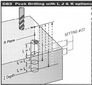
G83 Normal Peck Drilling Canned Cycle
a.k.a. Multi-peck drilling cycle
There are lots of drill variables to consider.
G99 = R plane return (rapid plane away from the part)
R = R-plane (drill position above the part)
Z = final Z depth; position of Z-axis at the bottom of the hole (i.e. thickness of the part) + the radius of the drill diameter
F = Feedrate in IPM
I = Size of first cutting depth; Initial peck depth
J = Amount to reduce cutting depth of each pass; peck depth reduction. The value reduces the following pecks by this amount.
K = Minimum depth of cut; minimum peck depth
What is I, J, K?
The drill goes to a depth in the hole. It retracts to clear chips and allow coolant into hole.
The drill goes back into hole. The drill is pecking.
J and K define the pecking measurements.
J defines peck depth reduction.
I is reduced by J until 0 measurement
K defines the minimum cut of depth.
During the pecking process, the CNC will adjust the cut so the minimum depth of cut is always used until 0 measurement.
The K value will switch on during G83.
Formula for pecking: FYI
G83 after 5x diameter of drill
I = 4X drill diameter, e.g. .5 dr dia = 2” depth
J = 2X drill diameter, e.g. .5 dr dia = 1”
K = 1x drill diameter, e.g, .5 = .5 depth
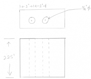
Is this a deep hole? The answer is based on the diameter of the drill. The drill size for this hole is 3/8″.
3/8″ * 3 = 1.125″ Therefore, yes this is a deep hole because the hole depth is the 2.25″.
The CNC must use G83 for a pecking cycle. The calculations for I, J, and K are below.
I = 4 * 3/8″ = 1.5″
J = 2 * 3/8″ = .75″
K = 1 * 3/8″ = .375″
Now, remember the formula for Z.
Z = thickness of part + radius of drill
Z = 2.25 + .1875
Z = 2.4375
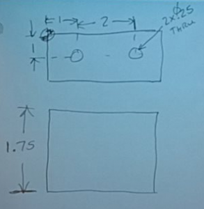
Is this a deep hole? The drill size for this job is .25.
.25 * 3 = .75
Yes, the hole is deeper than 3 times the drill diameter. This is deep hole.
G81 does not will not drive the drill all the way through the thru hole.
The program must use G83.
This is still a drilling operation. It is still a two-step operation with the first step using a center drill.
Material: Aluminum
Center drill: Header | Body | Footer
Drilling Code below:
|
T02 M06 (.25 Dr) G90 M06 G00 x1.0 y -1.0 G43 H02 Z1.0 M08 |
Header for Drilling |
|
G83 G99 R .1 I=1.0, J .5, K.25 (need another peck to break thru bottom) Z -1.875 [NOTE: Z = Total part thickness + radius of drill] F = calculated later (See explanation below) X3.0 |
Body |
|
G80 G00 Z1.0 M09 G28 G91 Z0 M05 M30 |
Footer |
CNC Drill Speed and Feed chart
On top chart, notice size of drill on left-hand column
Notice Feedrate columns at top: light | medium | heavy.
Light to medium feed for harder metals 1018, steels
Heavy feed use with plastics and aluminum
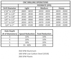
Bottom chart is about reductions in speed and feed for peck drilling.
Notice the Hole depth column. There are three questions necessary.
- “What is the diameter of the tool?”
- “What is the depth of the hole?” and,
- “How many times deeper is the hole than the diameter of the tool?”
For example:
Above, the deep hole was 3 times the diameter of the drill.
Find the speed and feed reductions on the bottom chart.
- “What is the diameter of the tool?” 1/4 drill
- “What is the depth of the hole?” 1.750″ hole
- “How many times deeper is the hole than the diameter of the tool?” 7 times
RPM = 350 * 3.82/ .5 = 2674
F = 2674 * .003 = 8.022 (In this example, we choose the light/medium feed for aluminum at .003 from chart)
The last step is to calculate the reductions.
S is reduced by 10% = 2674 * .9 = 2406
F is reduced by 10% = 8.022 * .9 = 7.2198
Practice Problem
