THE CARTESIAN COORDINATE SYSTEM
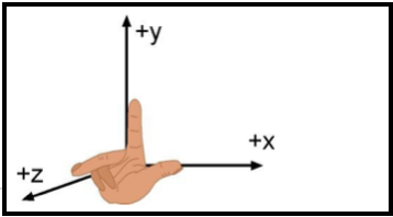
Cartesian coordinates allow one to specify the location of a point in the plane, or in three-dimensional space. The Cartesian coordinates or rectangular coordinates system of a point are a pair of numbers (in two-dimensions) or a triplet of numbers (in three-dimensions) that specified signed distances from the coordinate axis. First we must understand a coordinate system to define our directions and relative position. A system used to define points in space by establishing directions(axis) and a reference position(origin). A coordinate system can be rectangular or polar.
Just as points on the line can be placed in one to one correspondence with the real number line, so points in plane can be placed in one to one correspondence with pairs of real number line by using two coordinate lines. To do this, we construct two perpendicular coordinate line that intersect at their origins; for convenience. Assign a set of equally space graduations to the x and y axes starting at the origin and going in both directions, left and right (x axis) and up and down (y axis) point along each axis may be established. We make one of the number lines vertical with its positive direction upward and negative direction downward. The other number lines horizontal with its positive direction to the right and negative direction to the left. The two number lines are called coordinate axes; the horizontal line is the x axis, the vertical line is the y axis, and the coordinate axes together form the Cartesian coordinate system or a rectangular coordinate system. The point of intersection of the coordinate axes is denoted by O and is the origin of the coordinate system. See Figure 1.
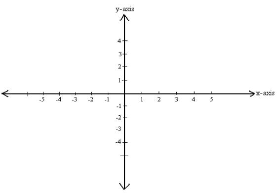
It is basically, Two Real Number Lines Put Together, one going left-right, and the other going up-down. The horizontal line is called x-axis and the vertical line is called y-axis.
THE ORIGIN
The point (0,0) is given the special name “The Origin”, and is sometimes given the letter “O”.
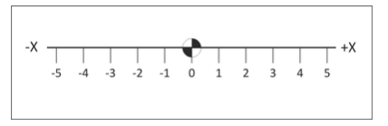
REAL NUMBER LINE
The basis of this system is the real number line marked at equal intervals. The axis is labeled (X, Y or Z). One point on the line is designated as the Origin. Numbers on one side of the line are marked as positive and those to the other side marked negative. See Figure 2.
CARTESIAN COORDINATES OF THE PLANE
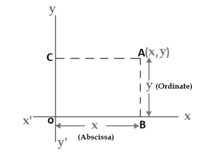
A plane in which a rectangular coordinate system has been introduced is a coordinate plane or an x-y-plane. We will now show how to establish a one to one correspondence between points in a coordinate plane and pairs of real number. If A is a point in a coordinate plane, then we draw two lines through A, one perpendicular to the x-axis and one perpendicular to the y-axis. If the first line intersects the x-axis at the point with coordinate x and the second line intersects the y-axis at the point with coordinate y, then we associate the pair (x,y) with the A( See Figure 2). The number a is the x-coordinate or abscissa of P and the number b is the y-coordinate or ordinate of p; we say that A is the point with coordinate (x,y) and denote the point by A(x,y). The point (0,0) is given the special name “The Origin”, and is sometimes given the letter “O”.
Abscissa and Ordinate:
The words “Abscissa” and “Ordinate” are words for the x and y values:
- Abscissa: X-value in a pair of coordinates. It is horizontal.
- Ordinate: Y-value in a pair of coordinates. It is vertical.
Negative Values of X and Y:
The Real Number Line, you can also have negative values.
Negative: start at zero and head in the opposite direction; See Figure 4
So, for a negative number:
- go left for x
- go down for y
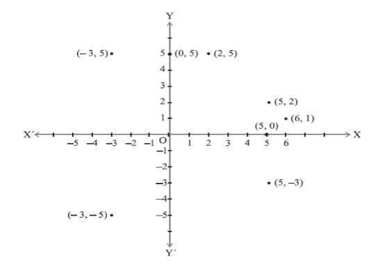
go left along the x axis 3 then go up 5 in the y-axis. (Quadrant II x is negative ,y is positive)
go left along the x axis 3 then go down 5 in the y-axis. (Quadrant III x is negative ,y is negative)


It is basically, a set of two Real Number lines.
Axis: The reference line from which distances are measured.
Example:
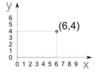
Go along the x direction 6 units then go up 4 units up in the y direction then “plot the dot”.
And you can remember which axis is which by:
The coordinates are always written in a certain order:
- the horizontal distance first,
- then the vertical distance.
Ordered pair:
The numbers are separated by a comma, and parentheses are put around the whole thing like this: (7,4)
Example: (7,4) means 7 units to the right (x-axis), and 4 units up (y-axis)
Practice
QUADRANTS
The coordinate axes divide the plane into four parts, called quadrants (See Figure 10). The quadrants are numbered counterclockwise, starting from the upper right, labeled I, II, III and IV with axes designations as shown in the illustration below.
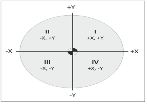
Four Quadrants:
The quadrants are the areas on each side of the axes. When we include negative values, the x and y axes divide the space up into 4 pieces:
Quadrants I, II, III and IV
(They are numbered in a counterclockwise direction)
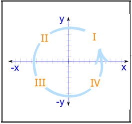
The first quadrant is on the top, right-hand side. Notice that the Roman numerals are in a counterclockwise direction.
- Points to the right of the Y-axis are positive in the X direction.
- Points to the left of Y-axis are negative in the X direction.
- Points above the X-axis are positive in the Y direction.
- Points below the X-axis are negative in the Y direction.
Another way to understand the quadrants follows:
- Quadrant I : both X and Y are positive (#, #)
- Quadrant II : X is negative, Y is still positive (- #, #)
- Quadrant III : both X and Y are negative (- #, – #)
- Quadrant IV : X is positive, Y is negative (#, – #)
By using the (X, Y) coordinate system all points in these two directions can be located. The X-value is always given first.
| Quadrant | X (Horizontal) | Y (Vertical) | Example |
| I | Positive | Positive | (3,2) |
| II | Negative | Positive | (-5, 2) |
| III | Negative | Negative | (-2, -1) |
| IV | Positive | Negative | (2, -5) |
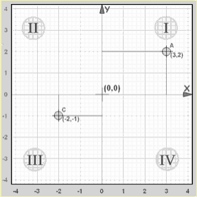
Example: The point “A” (3,2) is 3 units along the x-axis, and 2 units up the y-axis.
Both x and y are positive, so that point is in “Quadrant I”
Example: The point “C” (-2,-1) is 2 units along the x-axis in the negative direction, and 1 unit down the y-axis in the negative direction.
Both x and y are negative, so that point is in “Quadrant III”.
Here’s another example.
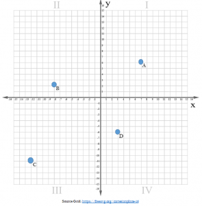
Point A is in Quadrant I, (7, 8)
Point B is in Quadrant II, (-8, 4)
Point C is in Quadrant III, (-12, -9)
Point D is in Quadrant IV, (3, -4)