27 Indentation Testing
Indentation hardness tests are used in mechanical engineering to determine the hardness of a material to deformation. Several such tests exist, wherein the examined material is indented until an impression is formed; these tests can be performed on a macroscopic or microscopic scale.
When testing metals, indentation hardness correlates roughly linearly with tensile strength, but it is an imperfect correlation often limited to small ranges of strength and hardness for each indentation geometry. This relation permits economically important nondestructive testing of bulk metal deliveries with lightweight, even portable equipment, such as hand-held Rockwell hardness testers.
Measuring hardness
Different techniques are used to quantify material characteristics at smaller scales. Measuring mechanical properties for materials, for instance, of thin films, cannot be done using conventional uniaxial tensile testing. As a result, techniques testing material “hardness” by indenting a material with a very small impression have been developed to attempt to estimate these properties.
Hardness measurements quantify the resistance of a material to plastic deformation. Indentation hardness tests compose the majority of processes used to determine material hardness, and can be divided into three classes: macro, micro and nanoindentation tests. Microindentation tests typically have forces less than 2 N (0.45 lb.). Classical hardness testing usually creates a number which can be used to provide a relative idea of material properties. As such, hardness can only offer a comparative idea of the material’s resistance to plastic deformation since different hardness techniques have different scales.
The equation-based definition of hardness is the pressure applied over the contact area between the indenter and the material being tested. As a result, hardness values are typically reported in units of pressure, although this is only a “true” pressure if the indenter and surface interface is perfectly flat.
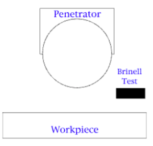
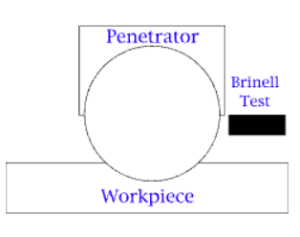
Brinell
Proposed by Swedish engineer Johan August Brinell in 1900, it was the first widely used and standardized hardness test in engineering and metallurgy.
Brinell testing is an indentation test. A penetrator is dropped on to a piece of metal. The size of the indentation is measured. See the figures below.
Brinell Hardness Testing:
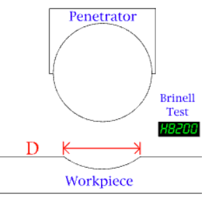
The measurement of the diameter (D) of the indentation relates to the Brinell Scale.
Videos for Brinell Hardness Test
Watch this 3:05 video which explains the Brinell Hardness Test by MaterialsScience2000, January 26, 2000.
Watch this 0:42 animated video that demonstrates the Brinell Hardness Test (youtube.com) by Innovatest Europe BV, November 14, 2019.
The large size of indentation and possible damage to test-piece limits its usefulness.
Rockwell
The Rockwell scale is a hardness scale based on indentation hardness of a material. The Rockwell test measures the depth of penetration of an indenter under a large load (major load) compared to the penetration made by a preload (minor load). There are different scales, denoted by a single letter, that use different loads or indenters. The result is a dimensionless number noted as HRA, HRB, HRC, etc., where the last letter is the respective Rockwell scale. Larger numbers correspond to harder materials.
When testing metals, indentation hardness correlates linearly with tensile strength.
The Rockwell hardness test can be conducted on several various hardness testers. All testers, however, fall under one of three categories. Bench model hardness testers can be found either in a digital or analog model. Digital bench models utilize a digital display and typically take more technical training to be able to operate, whereas the analog models are simpler to operate as well as very accurate and display results on a dial on the front of the machine. All bench model testers are usually found within a workshop or laboratory setting. Other testers are portable, and all portable testers will come in a digital model including a digital results screen similar to that of the bench digital model.
The determination of the Rockwell hardness of a material involves the application of a minor load followed by a major load. The minor load establishes the zero position. The major load is applied, then removed while still maintaining the minor load. The depth of penetration from the zero datum is measured from a dial, on which a harder material gives a lower measure. That is, the penetration depth and hardness are inversely proportional. The chief advantage of Rockwell hardness is its ability to display hardness values directly, thus obviating tedious calculations involved in other hardness measurement techniques.
The Rockwell test is very cost-effective as it does not use any optical equipment to measure the hardness based on the small indention made, rather all calculations are done within the machine to measure the indention in the specimen, providing a clear result in a manner in which is easy to read and understand once given. This also prevents any reworking or finishing needing to be done to the specimen both before and after testing. However, it is critical to double check specimens as the smallest indentions made from testing could potentially result in incorrect measurements in hardness, leading to catastrophe. After time, the indenter on a Rockwell scale can become inaccurate as well and need replacing to ensure accurate and precise hardness measurements.
The equation for Rockwell Hardness is
, where d is the depth in mm (from the zero-load point), and N and h are scale factors that depend on the scale of the test being used (see following section).
 , where d is the depth in mm (from the zero-load point), and N and h are scale factors that depend on the scale of the test being used (see following section).
It is typically used in engineering and metallurgy. Its commercial popularity arises from its speed, reliability, robustness, resolution and small area of indentation.
Legacy Rockwell hardness testers operation steps:
- Load an initial force: Rockwell hardness test initial test force is 10 kgf (98 N; 22 lbf); superficial Rockwell hardness test initial test force is 3 kgf (29 N; 6.6 lbf).
- Load main load: reference below form / table ‘Scales and values’.
- Leave the main load for a “dwell time” sufficient for indentation to come to a halt.
- Release load; the Rockwell value will typically display on a dial or screen automatically.
In order to get a reliable reading the thickness of the test-piece should be at least 10 times the depth of the indentation. Also, readings should be taken from a flat perpendicular surface, because convex surfaces give lower readings. A correction factor can be used if the hardness of a convex surface is to be measured.
Videos for Rockwell Hardness Test
Watch this 2:29 video Rockwell Hardness Test Scale C by MaterialsScience2000, January 26, 2013.
Watch this 039 animated video Rockwell Hardness Test by INNOVATEST Europe BV, November 14, 2019.
Rockwell Superficial
The superficial Rockwell scales use lower loads and shallower impressions on brittle and very thin materials. The 45N scale employs a 45-kgf load on a diamond cone-shaped Brale indenter and can be used on dense ceramics. The 15T scale employs a 15-kgf load on a 1⁄16-inch-diameter (1.588 mm) hardened steel ball and can be used on sheet metal.
Rockwell and Brinell indentation tests for hardness can be considered macro indentation tests.
Comparison Chart for Different Hardness Testing Numbers
Review this chart Brinell and Rockwell Hardness Conversion Chart | Rockwell, Rockwell Superficial, Brinell, Vickers, Shore Hardness Conversion Table by Engineers Edge, accessed and available online 30 November 2024.
This chart includes other testing numbers that are in the next chapters.
Derived from:
- Indentation hardness – Wikipedia, Available and accessed online 30 January 2024.
- Brinell scale – Wikipedia Available and accessed online 1 February 2024.
- Rockwell scale – Wikipedia Available and accessed online 1 February 2024, and
The Virtual Machine Shop (2011) http://www.jjjtrain.com/vms/eng_heat_treat/eng_heat_treat_07.html retrieved from Wayback Machine internet archive, 17 January 2024.
