17 Die Casting
Die casting uses molds (or “dies”) made of steel and is used to make castings of the non-ferrous lower temperature metals, such as aluminum, zinc, or bronze.
Common cast metals
- Zinc: the easiest metal to cast; high ductility; high impact strength; easily plated; economical for small parts; promotes long die life.
- Aluminum: lightweight; high dimensional stability for very complex shapes and thin walls; good corrosion resistance; good mechanical properties; high thermal and electrical conductivity; retains strength at moderately high temperatures.
- Magnesium: the easiest metal to machine; excellent strength-to-weight ratio; lightest alloy commonly die cast.
- Copper: high hardness; high corrosion resistance; highest mechanical properties of alloys die cast; excellent wear resistance; excellent dimensional stability; strength approaching that of steel parts.
- Silicon tombac: high-strength alloy made of copper, zinc and silicon. Often used as an alternative for investment cast steel parts.
- Lead and tin: high density; extremely close dimensional accuracy; used for special forms of corrosion resistance. Such alloys are not used in foodservice applications for public health reasons. Type metal, an alloy of lead, tin and antimony (with sometimes traces of copper), is used for casting hand-set type in letterpress printing and hot foil blocking. Traditionally cast in hand jerk molds, now predominantly die cast after the industrialization of the type foundries. Around 1900 the slug casting machines came onto the market and added further automation, with sometimes dozens of casting machines at one newspaper office.
The mold is machined from two blocks of steel, and consequently, the castings have a much smoother surface finish and smaller radii and draft than parts made from sand castings
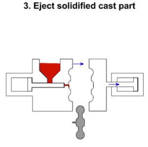
In die casting, the molten metal is poured in a piston.
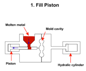
The molten metal is injected by a piston into the mold where it cools and solidifies.
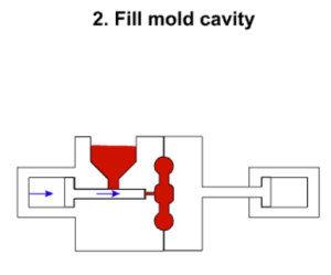
Afterwards, the mold is pulled apart by hydraulic cylinders and the casting removed. The entire process is automated and produces parts rapidly.
Design Geometry
There are a number of geometric features to be considered when creating a parametric model of a die casting:
- Draft is the amount of slope or taper given to cores or other parts of the die cavity to allow for easy ejection of the casting from the die. All die cast surfaces that are parallel to the opening direction of the die require draft for the proper ejection of the casting from the die. Die castings that feature proper draft are easier to remove from the die and result inhigh-quality surfaces and more precise finished product.
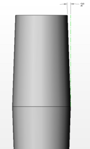
Profile of a drafted cylinder with a draft dimension. CC BY-SA
Video about applying draft
Watch this 1:35 video Draft Application in Die Casting by North American Die Casting Association
- Fillet is the curved juncture of two surfaces that would have otherwise met at a sharp corner or edge. Simply, fillets can be added to a die casting to remove undesirable edges and corners.
Video about adding fillets
Watch this 1:06 video about Adding Fillets to your Die Casting Design by North American Die Casting Association
- Parting line represents the point at which two different sides of a mold come together. The location of the parting line defines which side of the die is the cover and which is the ejector.
Video about Parting Line
Watch this 1:18 video Die Casting Geometry: Parting Line by North American Die Casting Association
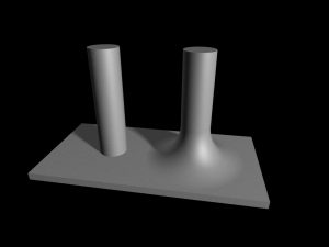
- Bosses are added to die castings to serve as stand-offs and mounting points for parts that will need to be mounted. For maximum integrity and strength of the die casting, bosses must have universal wall thickness.
Video about Boss
Watch this 1:24 video Adding Bosses to Your Cie Casting Design by North American Die Casting Association
- Ribs are added to a die casting to provide added support for designs that require maximum strength without increased wall thickness.
Video about Ribs
Watch this 1:28 video Adding Ribs to Your Die Casting Design by North American Die Casting Association
- Holes and windows require special consideration when die casting because the perimeters of these features will grip to the die steel during solidification. To counteract this effect, generous draft should be added to hole and window features.
Video about Holes and Windows
Watch this 1:40 video Handling Designs with Holes & Windows by North American Die Casting Association
Equipment
There are two basic types of die casting machines: hot-chamber machines and cold-chamber machines.[14] These are rated by how much clamping force they can apply. Typical ratings are between 400 and 4,000 st (2,500 and 25,400 kg).[8]

Hot chamber die casting, also known as gooseneck machines, rely upon a pool of molten metal to feed the die. At the beginning of the cycle the piston of the machine is retracted, which allows the molten metal to fill the “gooseneck”. The pneumatic- or hydraulic-powered piston then forces this metal out of the gooseneck into the die. The advantages of this system include fast cycle times (approximately 15 cycles a minute) and the convenience of melting the metal in the casting machine. The disadvantages of this system are that it is limited to use with low-melting point metals and that aluminum cannot be used because it picks up some of the iron while in the molten pool. Therefore, hot-chamber machines are primarily used with zinc-, tin-, and lead-based alloys.
Video about Hot Chamber Die Casting
Watch this 1:12 video Hot Chambe Die Casting Process by North American Die Casting Association

These are used when the casting alloy cannot be used in hot-chamber machines; these include aluminum, zinc alloys with a large composition of aluminum, magnesium and copper. The process for these machines start with melting the metal in a separate furnace. Then a precise amount of molten metal is transported to the cold-chamber machine where it is fed into an unheated shot chamber (or injection cylinder). This shot is then driven into the die by a hydraulic or mechanical piston. The biggest disadvantage of this system is the slower cycle time due to the need to transfer the molten metal from the furnace to the cold-chamber machine.
Video about Cold Chamber Die Casting
Watch this 1:12 video Cold Chamber Die Casting Process by North American Die Casting Association
Derived from Die casting – Wikipedia available and accessed August 3, 2024, and The Virtual Machine Shop available and accessed at http://www.jjjtrain.com/vms/eng_castings/eng_castings_04.html via the WayBack Machine internet archive 16 January 2024.
