Vocabulary Terms
- PERSPECTIVE
- OBLIQUE DRAWING
- ISOMETRIC DRAWING
- ONE-VIEW DRAWING
- TWO-VIEW DRAWING
- ORTHOGRAPHIC PROJECTION
- HIDDEN SURFACES
- CURVED SURFACES
- INCLINED SURFACES
Now that you have learned about the kinds of lines found on prints, the next step is to develop your visualization abilities. The ability to ”see” technical drawings; that is to ”think in three dimensions,” is the most important part of this course. Since most engineering and architectural prints utilize some form of orthographic projection (multi-view drawing), that type of drawing will be emphasized.
Before going into a study of orthographic projection, you should be able to recognize several other types of drawings. They are; 1. Perspective drawing, 2. Oblique drawing, and 3. Isometric drawing. As a group, they are called “pictorial drawings”. They are found on prints and are easy to visualize, so let’s look at their differences.
Perspective
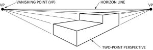
Perspective is the most realistic form of drawing. Artists use one-point perspective, two-point (shown here), and three point to create visual depth. Perspectives are used by architects and for industrial pictorials of plan layouts, machinery, and other subjects where realism is required. Objects drawn in perspective grow smaller as they recede into the horizon.
Oblique
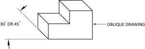
Oblique drawings are drawn with one plane (front) of the object parallel to the drawing surface. The side, or other visible part of the object is generally drawn at 30◦ or 45◦. Note that only the side is on an angle. Many times these types of drawing are not drawn to scale. The receding lines are drawn at 45◦ or 30◦ and will be drawn at a different scale as the vertical and horizontal lines. This make the drawing seem “out of shape”. This type of drawing is not used very often in industry.
Isometric
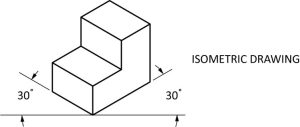
Isometric drawings have less distortion than oblique drawings, and are used more frequently by industry for that reason. An isometric drawing has both visible surfaces drawn at 30◦. These are the most used type of drawings in the piping industry and take a good deal of practice to fully understand how to draw. They best represent what is being built and what it will look like from the different sides with one drawing.
Questions
Directions: Name the types of drawings. Check your own answers.
Single View
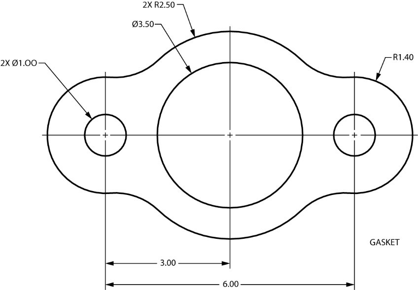
A single view of an object is sometimes all that is needed for a complete visual explanation. When dimensions, material, and other information is Included, an object requiring only a single view is easy to understand.
Most one-view drawings are of flat objects, made from materials such as sheet metal and gasket stock. Spherical objects, such as a cannonball, would require only one view and a note indicating the material and diameter of the sphere.
The object shown in the one-view drawing below could be made of any appropriate material that might be specified. In appearance, it is much like the gasket used as part of the cooling system on many cars. All that would need to be noted is the material type and thickness required.
Two View
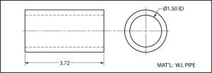
Sometimes “two-view” drawings are use on prints. Two views may be all that is needed to show the shape of an object. Objects that are cylindrical, such as a length of pipe, are usually shown on a print with two views. In such a case, two views is sufficient to explain the shape. Notice in the two-view drawing shown below that the length of the pipe is shown in one view, while the diameter is called out in the other. Without the view on the right, what might this shape be mistaken for? Square tube, channel…
Orthographic Projection
Orthographic projection is a name given to drawings that usually have three views. Often, the three views selected are the top, front, and right side. It is possible, of course, to select other views such as the left side or bottom. Generally, though, it’s the top, front and right side that are traditionally seen by the person reading prints.
Since most prints make use of the orthographic projection system, and because the top, front, right side views are most often used, it is important that you have their order, or arrangement on the print fixed in your mind. To help you understand this system, think of a chalkboard eraser, a short length of 2″ x 4″ lumber, or a common brick. It looks like this:
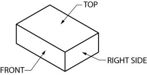
When seen on a print, using orthographic projection, it would appear like this.
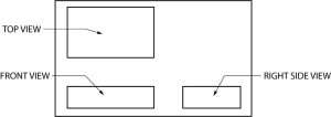
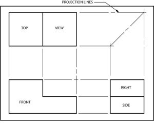
This system of orthographic projection may be difficult to understand or visualize at first, but you will grasp it with some practice. Here’s a basic example of how it works, using a simple object.
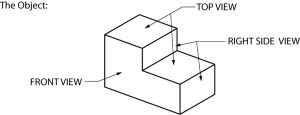
Orthographic projection does not show depth, so the object shown above will appear flat. With practice, however, you will learn to scan the three views and “read” depth into them. Remember that the location of the top, front and right side views does not change. The projection lines between the orthographic views below show the height, width, and depth relationship that exists between each view and the other two views.
In case you did not understand the three-view on the last page, let’s take another look at the same thing. This time numbers will be used for identification for the surfaces.
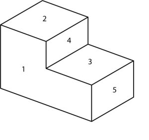
Using orthographic projection, the object with the surfaces numbered appears like this:
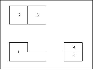
Notice that the front view (1) is the key to the drawing, because it most clearly shows the shape of the object. It tells you the object is “L” shaped from the front. The other two views don’t tell you much by themselves. By looking at surface 1, however, you can see that 2 is taller than 3. Therefore, in “reading” the surfaces, 2 should appear to be closer to you than 3. Now look at 4 and 5. Which surface is projected closest to you?·
Answer: Surface 5 (rotate and place at bottom of layout)
Now draw a simple box and tape all sides together to form a cube. The cube will be 2”x 2”x 2”. Once the instructor has approved your drawing you will proceed to cut out and tape edges together to form a cube.
Online Activity
Watch this online activity to help you understand orthographic projections.
Orthographic Projections #1 by Wisc-online.com
Visualization Quiz
Click here to get a copy of the pages to print.
You may be wondering at this point why something like orthographic projection is used on prints when isometric or oblique drawings are so much easier to visualize. The answer is that both of those types of pictorials are used for relatively uncomplicated drawings. When an object is complex, however, neither can equal the orthographic system for clear presentation of dimensions, notes, and configuration details.
Hidden Surfaces
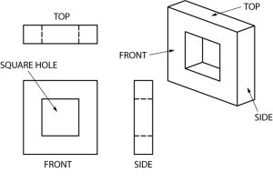
Another advantage of orthographic projection is that it allows the person reading the print to have the ability to see the inside, or surfaces of an object which normally could not be seen.
With complicated objects this can become very useful.
In the drawing below, the hidden line in the right side view represents the entire surface of the flat area between the two higher sides.
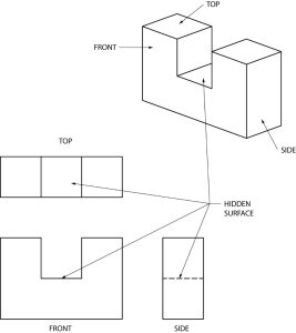
In this example, the hidden lines result from a square hole through the middle of the object.
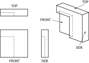
The hidden lines in this example are there because a part of one corner of the front surface was cut away, or “recessed.
Practice
Directions: Draw the hidden lines which are missing in the views below. Each problem has one incomplete view.
Click here to get a copy of the worksheet to print.
Curved Surfaces
Curved surfaces are perhaps tricky to “see” until you remember that the curve is only shown in one view. You must put the curve in the other views yourself, through visualization. Try to think that when there is a sharp change of direction like at a corner, then that will produce a line visible in another view. When the change of direction is smooth like a curve, no line will be seen.
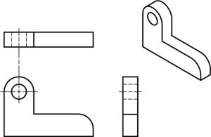
Here’s another example of curved surfaces:
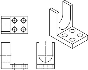
Practice with curved surfaces
Directions: Draw the lines which are missing in the views below. Each problem has one incomplete view. Do not draw center lines.
Click here to get a copy of the worksheet to print.
Inclined Surfaces
Inclined surfaces are those which are at an angle, or slanted. In other words, they are surfaces which are neither horizontal nor vertical. In viewing orthographic drawings you need to be alert to angles and inclined surfaces, for they are often found on the prints you will be reading later.
Notice the hidden line in the right view created by the inclined surface on this object:
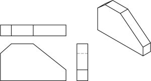
Here is an object with two inclined surfaces.
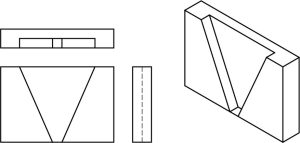
Practice with inclined surfaces
Directions: Draw the lines which are missing in the views below. Each problem has one incomplete view.
Click here to get a copy of the worksheet to print.
Practice Online
Try these online activities to help you with visualization of a part on a print.
Pictorial Drawings by Wisc-online.com
Print Reading: Three-Step Block by Wisc-online. com
Print Reading: Slotted Block by Wisc-online.com
Print Reading: Holder by Fox Valley Community College via Wisc-online.com
This following activity shows and inclined surface.
Print Reading: Mounting Wedge by Wisc-online.com
The following links offer practice with identifying the correct isometric views.
Brain Exercise: Visualization #1 by Wisc-online.com
Brain Exercise: Visualization #2 by Wisc-online.com
Brain Exercise: Visualization #3 by Wisc-online.com
Questions